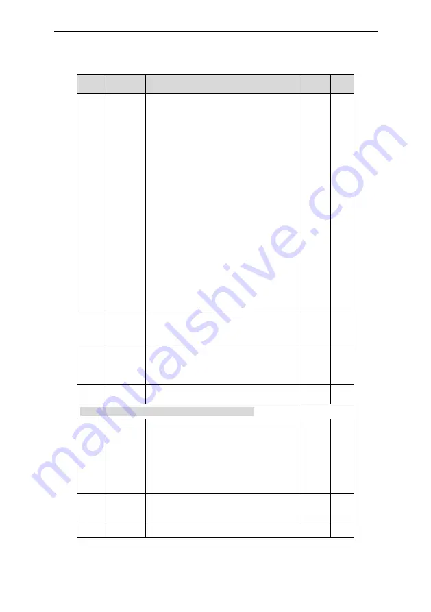
Astraada DRV-24 frequency inverters Function Parameters
71
Functio
n code
Name
Detailed instruction of parameters
Defaul
t value
Modify
changes, it needs more time to offset the
impact of continuous working and the
integration will change with the trend.
1: Stop integral adjustment when the
frequency reaches the upper and low limit. If
the integration keeps stable, and the trend
between the reference and the feedback
changes, the integration will change with the
trend quickly.
LED tens:
0:The same with the setting direction; if the
output of PID adjustment is different from the
current running direction, the internal will
output 0 forcedly.
1:Opposite to the setting direction
LED hundreds:
0: Limit to the maximum frequency
1: Limit to A frequency
LED thousands:
0:A+B frequency, buffer ACC/DEC is invalid for
the main reference A frequency source
1:A+B frequency, buffer ACC/DEC is valid for
the main reference A frequency source and the
ACC/DEC is determined by time 4 of P08.04
P09.14
Proportiona
l gain at low
frequency
(Kp)
0.00~100.00
1.00
○
P09.15
PID
command
of ACC/DEC
time
0.0~1000.0s
0.0s
○
P09.16
PID output
filter time
0.000~10.000s
0.000s
○
P10 Group Simple PLC and multi-step speed control
P10.00
Simple PLC
means
0: Stop after running once. The inverter has to
be commanded again after finishing a cycle.
1: Run at the final value after running once.
After finish a signal, the inverter will keep the
running frequency and direction of the last run.
2: Cycle running. The inverter will keep on
running until receiving a stop command and
then, the system will stop.
0
○
P10.01
Simple PLC
memory
selection
0:Power loss without memory
1:Power loss memory
;
PLC record the running
stage and frequency when power loss.
0
○
P10.02 Multi-step 100.0% of the frequency setting corresponds to
0.0%
○
Summary of Contents for AS24DRV4075
Page 1: ...Operation Manual Astraada DRV 24 Frequency inverters ...
Page 2: ......


