ANISOPRINT Composer User Manual Download Page 19


Composer User Manual

7.3. Loading materials

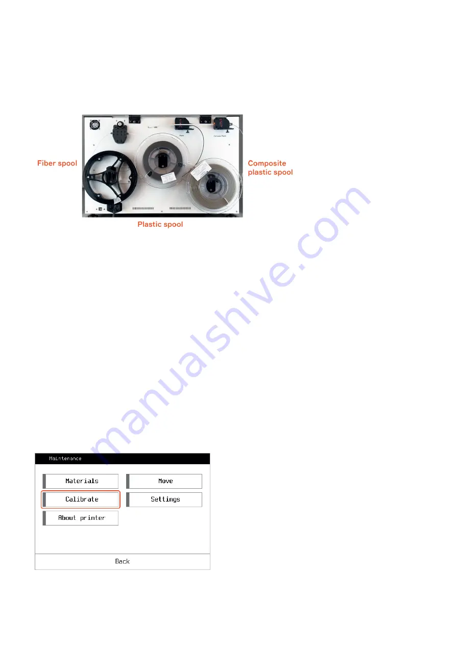
1. Take the 3 spools (plastic, composite plastic, and fiber) out of package and place them
onto the holders.

2. On the Composer screen, click 

Maintenance > Materials >

 and choose the material you want to load. Follow

instructions on the screen.

NOTICE: 

Plastic can leak out of the composite heat block inlet during plastic filament loading in the composite

extruder. Just remove the leaked plastic with tweezers to prevent dripping of the plastic on the printed part. 

7.4. Buildplate calibration

Your Composer had already been pre-calibrated before shipping, but due to transport vibrations, it could be
uncalibrated. Thus, you may need to go through the entire calibration procedure after the printer installation.

NOTICE

: Clean and preheat the nozzles and the buildplate to its printing temperatures before all the calibration

procedures (buildplate, Z axis, Z-offset) to prevent incorrect calibration.

You need to go through the buildplate calibration procedure after any changes affecting the positioning of the
buildplate, e.g. shaking or moving the printer. While printing a large part occupying the whole buildplate area, you
can notice layer thickness varies from one end of the part to another, which as well means the buildplate requires
recalibration.

 19 / 57

Summary of Contents for Composer

Page 1: ...Composer User Manual Composer User Manual by Anisoprint Support 1 57...

Page 2: ...te calibration 19 7 5 Z axis calibration 20 7 6 Z offset calibration 20 7 7 XY offset calibration 21 7 8 Test print 23 7 9 In situ tuning of printing settings 24 7 10 WI FI connection 28 7 11 Network...

Page 3: ...11 3 Fiber is not extruded from the nozzle 44 11 4 Strings and poor surface quality of printed part 44 11 5 Plastic leaks out of the composite heat block inlet 45 11 6 Fiber is clogged inside the com...

Page 4: ...General Precautions Carefully study all precautions before using the printer When in operation the user should follow all operation precautions for electrical equipment An explanatory note to graphic...

Page 5: ...at carbon fiber is a good electrical conductor The flow of current through carbon fiber leads to its instant ignition which may result in injuries and equipment failure WARNING do not place the printe...

Page 6: ...les and recommendations described in this User Manual Product certificate 181299324 Certificate is valid from 09 11 2018 through 08 11 2021 Product and services certification authority Technick sk obn...

Page 7: ...is forming The plastic extruder has one inlet for plastic filament and one nozzle The technology allows manufacturing high quality reinforced materials while using the flexibility of shapes and a wid...

Page 8: ...ser Manual 6 Delivery package Items in the package 1 Composer CFC printer 1 pc 2 Plastic filament spool 2 pc 3 Anisoprint CCF 1 5k fiber spool 1 pc 4 Tool kit 1 pc 5 Personal protective equipment kit...

Page 9: ...the main screen which brief description is given below 1 Plastic extruder temperature settings button 2 Buildplate temperature settings button 3 Composite extruder temperature settings button 4 print...

Page 10: ...filaments and composite fiber B Calibration of the buildplate Z axis print head Z offset C Printer connection settings D Key information about the printer serial number version info build date Use axe...

Page 11: ...Composer User Manual Select movement increment Use home positioning buttons for tool homing 11 57...

Page 12: ...l XY coordinates of extruder and Z coordinate of buildplate Also you can control material supply To do it press Extruders button Here the following options are available Retract supply plastic filamen...

Page 13: ...Composer User Manual Retract supply composite fiber in composite extruder Retract supply plastic filament in composite extruder 13 57...

Page 14: ...Composer User Manual Select increment for material retract supply Control material feed coordinates 14 57...

Page 15: ...Composer User Manual Change active extruder Initiate fiber cutting mechanism 15 57...

Page 16: ...Composer User Manual Switch on off nozzle blowing fan E Composer axes positioning button Here the following options are available NOTE these parameters directly affect the printer functionality 16 57...

Page 17: ...start printing Unpack the printer and place it on a reliable flat surface protected from strong vibrations Adjust the printer feet to compensate for any unevenness of the surface if needed 1 Remove b...

Page 18: ...tion bracket on the right for A4 and on the left for A3 Composers The size and color may vary with the printer model 5 Plug in the power cable 6 Calibrate the buildplate with an in built procedure at...

Page 19: ...already been pre calibrated before shipping but due to transport vibrations it could be uncalibrated Thus you may need to go through the entire calibration procedure after the printer installation NO...

Page 20: ...tion The distance between the buildplate and the plastic nozzle tip is quite an important parameter affecting the quality of your prints You need to go through this procedure every time you replace th...

Page 21: ...nthead Comp Z offset and go through the built in calibration procedure by following the instructions on the screen 7 7 XY offset calibration X and Y offsets are the physical distances between the tips...

Page 22: ...tes from the middle position of the central cells like it is shown in the reference scheme you need to change your XY offsets values i e calibrate it In order to calibrate XY offsets for every axis fi...

Page 23: ...est You can find the Wall bracket for the particular profile in the Aura Welcome window Use recommended adhesive for your plastic filament e g Magigoo Original for transparent PETG or Magigoo PA for p...

Page 24: ...s will be surrounded by plastic ones Make sure the plastic and fiber perimeters do not intersect and fiber perimeters are laid without displacements Inspect the printed part paying special attention t...

Page 25: ...sitions Extruders stay hot during the pause You can see all the control capabilities over the paused print in the picture below Here the following settings are available 1 Cancel the print 2 Cool or h...

Page 26: ...ases or decreases predefined temperature on set increment 0 C by default can be varied within a range of 100 to 100 C Note that the temperature is limited by 270 C for extruders and 120 C for buildpla...

Page 27: ...utton is pressed in the printing mode is shown below Here the following settings are available 1 3 and 4 buttons are the same as for paused print 2 Correct Z If the first layer of the print is too thi...

Page 28: ...n a please turn the printer off and on and wait for one minute the network bridge booting process takes about a minute after power on If the NW ver is 0 1 please follow additional instructions marked...

Page 29: ...ly 4 times a day if a new version is available Note 1 The updates are performed from Ubuntu Snap Store if your printer is behind a firewall please check the following document to make sure that these...

Page 30: ...2mm hex key from the tool kit loosen the side screws of the fan bracket Remove the fan bracket carefully it should hang on wires 2 Heat the plastic extruder to the printing temperature 270 C for Smoo...

Page 31: ...if the under extrusion occurs Follow the next steps to clean the plastic nozzle 1 Heat the plastic extruder to the printing temperature 270 C for Smooth PA 2 Clean the nozzle with a cleaning needle f...

Page 32: ...the extruder cleaning is recommended before each print This will ensure the successful printing of the parts without fiber clogging CAUTION all extruder parts can be hot 1 Heat composite extruder up t...

Page 33: ...tools 3 Insert the barbed needle from the set of cleaning tools into the composite nozzle Spinning the needle push it through the extruder until the end of the needle is in the inlet hole of the extru...

Page 34: ...Composer User Manual 34 57...

Page 35: ...Composer User Manual 4 Remove material pushed out of the inlet of the extruder with tweezers 35 57...

Page 36: ...6 From the main screen go to Maintenance Move Extruders change Step to 10 mm and feed 50 mm of the composite plastic filament press V button 5 times You should see clean plastic exiting from the nozz...

Page 37: ...rst layers of the product it is recommended to clean the surface of the glass before each print with a damp cloth 9 Printing materials 9 1 Plastics There are two different plastics included in the Del...

Page 38: ...fiber co extrusion process CFC is applied as a matrix material in 3D printed composite parts reinforced with continuous fibers The material is supplied as filaments with cross sectional diameter of 1...

Page 39: ...les for any plastic with a melting point below 270 C 9 2 Reinforcing fiber A specially prepared patented composite fiber Anisoprint CCF is used for printing with reinforcement It provides a high quali...

Page 40: ...CCF Composite Carbon Fiber and CBF Composite Basalt Fiber Being heated above 40 C for a long time more than several minutes carbon and basalt fibers become brittle and improper for printing 10 Softwa...

Page 41: ...4 Buildplate 5 Origin of the coordinate system 6 View toolbar zoom pan rotate etc 7 Main tabs 10 2 Slicing the model To prepare your model for printing you should go through the following steps 1 In t...

Page 42: ...ne of the following formats stl step stp 3ds obj 3 Adjust printing settings in the SLICING panel from the main tabs and click GENERATE 4 After a successful generation of the code you will be offered t...

Page 43: ...ible graphics card e g ATI Radeon 3000 series Nvidia GTX 300 series Display resolution 1920 x 1080 Intel Core i3 or AMD Athlon 64 400 MB hard disk space 8 GB RA 11 Troubleshooting There are several is...

Page 44: ...acement 2 procedure p 8 1 11 3 Fiber is not extruded from the nozzle 1 Check whether the fiber is correctly loaded in the feeder Whether the fiber comes to the print head 2 Check whether the temperatu...

Page 45: ...Go through the PLASTIC NOZZLE REPLACEMENT https support anisoprint com wp admin admin ajax php plastic nozzle replacement 2 procedure p 8 1 if required 11 5 Plastic leaks out of the composite heat blo...

Page 46: ...e material specification if required NOTICE lack of composite fiber in the heat block or stop of its feed can cause plastic leak of the composite heat block inlet This can happen during the composite...

Page 47: ...ruder channel cleaning p 8 3 4 Insert the barbed needle from the set of cleaning tools into the composite nozzle Spinning the needle push it through the extruder until the end of the needle is in the...

Page 48: ...Composer User Manual 48 57...

Page 49: ...Composer User Manual 5 Remove material pushed out of the inlet of the extruder with tweezers 49 57...

Page 50: ...pushing out of the inlet hole of the extruder 7 From the main screen go to Maintenance Move Extruders change Step to 10 mm and feed 50 mm of the composite plastic filament press V button 5 times You s...

Page 51: ...m COMPOSITE EXTRUDER CHANNEL CLEANING p 8 3 2 Using the 2mm hex key from the Tool Kit loosen the side screws of the fan bracket Remove the fan bracket carefully the fan bracket stays hang on wires 3 U...

Page 52: ...Composer User Manual 4 Using the wrench key or pliers unscrew the fiber guiding bushing 52 57...

Page 53: ...is clogged inside the fiber guiding bushing clean it with a needle from the set of cleaning tools by pushing the fiber out of the bushing NOTICE fiber guiding bushing consists of two parts If you face...

Page 54: ...se order 11 8 Fiber is broken before the cutter in the PTFE guiding tube This may happen if the cutter is positioned incorrectly so the fiber could not pass through it and was broken in the PTFE guidi...

Page 55: ...Composer User Manual 2 Remove the excessed fibers from the tube 55 57...

Page 56: ...Composer User Manual 3 Connect the tube to the printing head 56 57...

Page 57: ...Composer User Manual Powered by TCPDF www tcpdf org 57 57...

Reviews: