


UG-570
AD9361 Reference Manual
| Page 50 of 128
RECEIVED SIGNAL STRENGTH INDICATOR (RSSI)
OVERVIEW
Given the wide variety of applications for which the
AD9361
is
suited, the received strength signal indicator (RSSI) many be
setup in one of several configurations, allowing the user to
optimize the RSSI to produce extremely accurate results with a
minimum of BBP interaction. RSSI accuracy is inherently very
good but can be improved through various means, including the
gain step calibration.
The
AD9361
measures RSSI by measuring the power level in dB
and compensating for the receive path gain. The various options
available support both TDD and FDD applications. Note that the
RSSI value is not in absolute units. Equating the RSSI readback
value to an absolute power level (for example, in dBm) requires a
factory calibration. To calibrate the RSSI word to an absolute
reference, inject a signal into the antenna port of the completed
system and read the RSSI word. From this test, generate a
correction factor that equates the RSI word to the injected signal
level at the antenna port. This calibration is separate from the
gain step calibration.
MODE SELECT AND MEASUREMENT DURATION
The RSSI Mode Select bits determine what event starts or restarts
the RSSI algorithm and clears the accumulator, per Table 33.
If the Default RSSI Meas Mode bit is set, then the duration is
a simple power-of-two value shown in Equation 18.
If the Default RSSI Meas Mode bit is clear, then non-power-of-two
durations are possible per Equation
19. The four duration
values are stored in Register 0x150 and Register 0x151.
Duration is always Rx sample-rate cycles.
RSSI WEIGHTING
If the Default RSSI Meas Mode bit is clear, then the RSSI
measurement duration consists of up to 4 values summed
together. Since each value can be different, each value must be
correctly weighted by its duration in Rx samples. Weighting is
calculated per Equation 20. If the Default RSSI Meas Mode bit is
set, the
AD9361
automatically populates Multiplier 0 with 0xFF
and the other multipliers with 0x00. When calculated correctly,
the total of all four weights added together will be 255 (d).
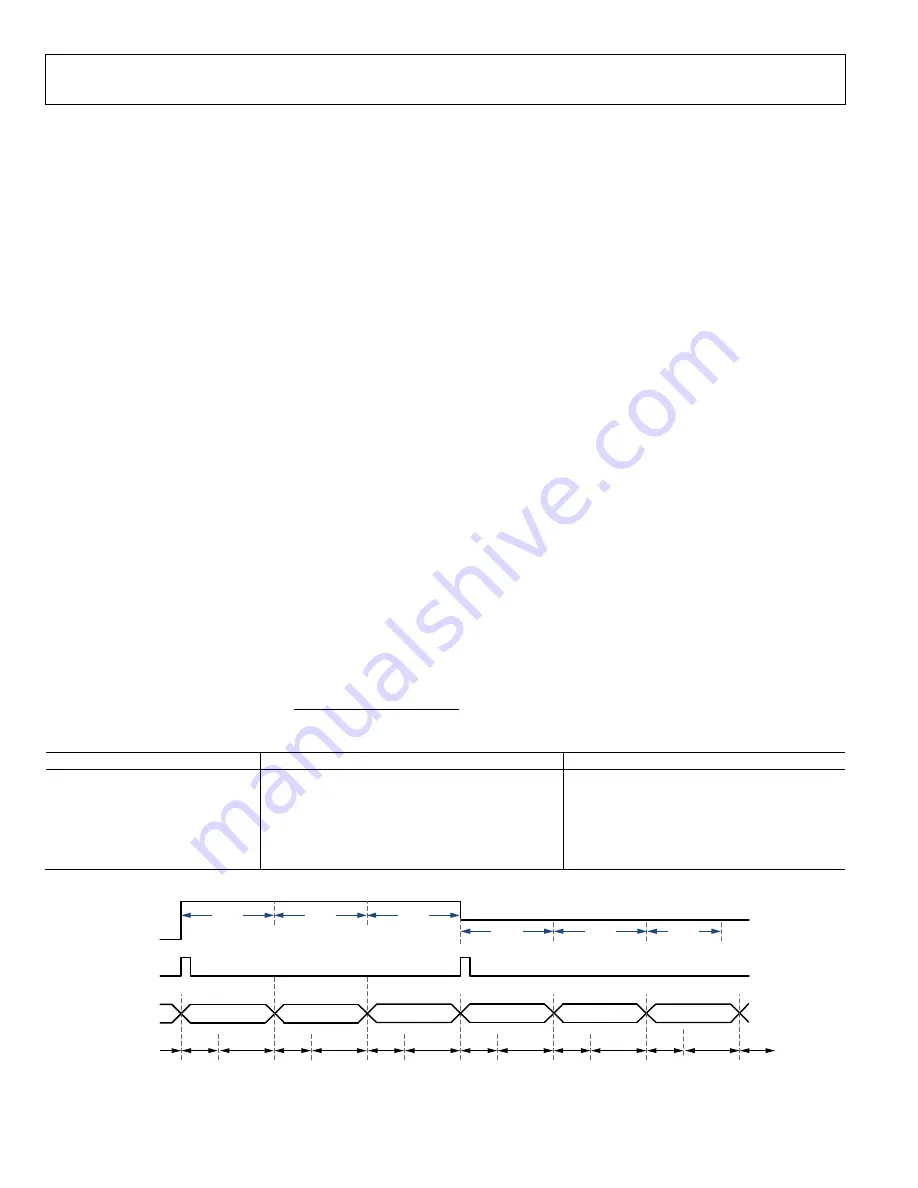
RSSI DELAY AND RSSI WAIT
When the RSSI algorithm (re)starts, the
AD9361
first waits for
the Rx signal path to settle. This is the RSSI delay and it is clocked
at the Rx sample rate divided by 8. From this point on, the RSSI
algorithm alternates between measuring RSSI and waiting to
measure RSSI. The purpose of the RSSI Wait value is to align the
RSSI measurement start with boundaries (such as slot
boundaries) and is most useful in FDD applications. Figure 27
shows the use of RSSI Wait, RSSI Delay, and the measurement
duration.
2
:
(18)
∑
2
:
(19)
255
:
(20)
Table 33.RSSI Mode Select
RSSI Mode Select
The RSSI Algorithm (re)starts when:
Useful For
000
AGC in Fast Attack Mode Locks the Gain
TDD
001
EN_AGC pin is pulled high
TDD, measuring a symbol late in the burst
010
AD9361
enters Rx mode
TDD
011
Gain change occurs
FDD
100
SPI write to Register 0x158[D5]
FDD
101
Gain change occurs or EN_AGC pin pulled high
FDD
Figure 27. RSSI Used in FDD Application
Rx SIGNAL
ENVELOPE
RSSI SYMBOL
RSSI STATE
...
...
ACCUMULATOR RESETS IF A GAIN CHANGE OCCURS. USEFUL FOR FDD MODE.
DIAGRAM NOT TO SCALE.
SLOT
SLOT
SLOT
SLOT
SLOT
SLOT
RSSI
DELAY
RSSI
DELAY
RSSI
CALC
RSSI
WAIT
RSSI
CALC
RSSI
CALC
RSSI
CALC
RSSI
CALC
RSSI
CALC
RSSI
WAIT
RSSI
WAIT
RSSI
WAIT
...
GAIN CHANGE
1
166
8-
028
Rev. A


