


Installation
26
NXP-TPI/4 NetLinx Touch Panel Interface
8.
The transparent plastic AMX cover can be removed to gain better access and visibility of the front
LEDs and pushbuttons.
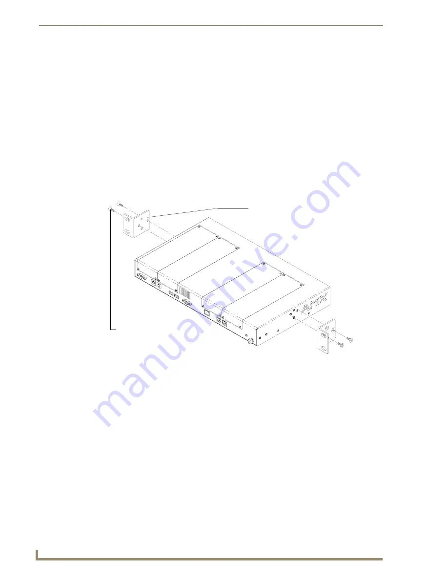
Other Mounting Options
The TPI/4 comes included with rack ears that can be rotated 90° in any direction to accommodate several
different mounting options, including tabletop, under/over the table, and vertical wall mounting. Rotate
the mounting brackets to mount the NXP-TPI/4 on top of a flat surface, under-table, or vertically. The
following steps apply to all of these mounting options.
1.
Discharge any static electricity from your body by touching a grounded metal object or the
grounding bolt shown in FIG. 15.
2.
Disconnect the NetLinx connector from the Central Controller, the RS-232, Ethernet, USB, audio,
and optional video/graphic wiring from the source equipment.
3.
Position and install the mounting brackets, as shown in FIG. 16, using the screws supplied with the
unit. The mounting brackets can be rotated to accommodate your mounting needs.
4.
Connect any applicable wires to the NXP-TPI/4.
Refer to the
Wiring Guidelines for the NXP-TPI/4
section on page 15 for wiring diagrams and pinout
descriptions.
5.
Connect the terminal NetLinx wiring to the Central Controller, RS-232, Ethernet, ICSNet, USB,
and optional video/graphic wiring to the source equipment.
FIG. 16
Installing mounting brackets
Mounting brackets (rack ears)
Four Phillips flat-head
screws
Summary of Contents for NetLinx NXP-TPI/4
Page 38: ...TPI 4 and Panel Interface Setup 32 NXP TPI 4 NetLinx Touch Panel Interface...
Page 60: ...Upgrading TPI 4 Firmware 54 NXP TPI 4 NetLinx Touch Panel Interface...
Page 138: ...Troubleshooting 132 NXP TPI 4 NetLinx Touch Panel Interface...
Page 147: ...Appendix 141 NXP TPI 4 NetLinx Touch Panel Interface...


