Installation Procedures: 12" and 15" Panels
46
12” and 15” Modero Touch Panels
6.
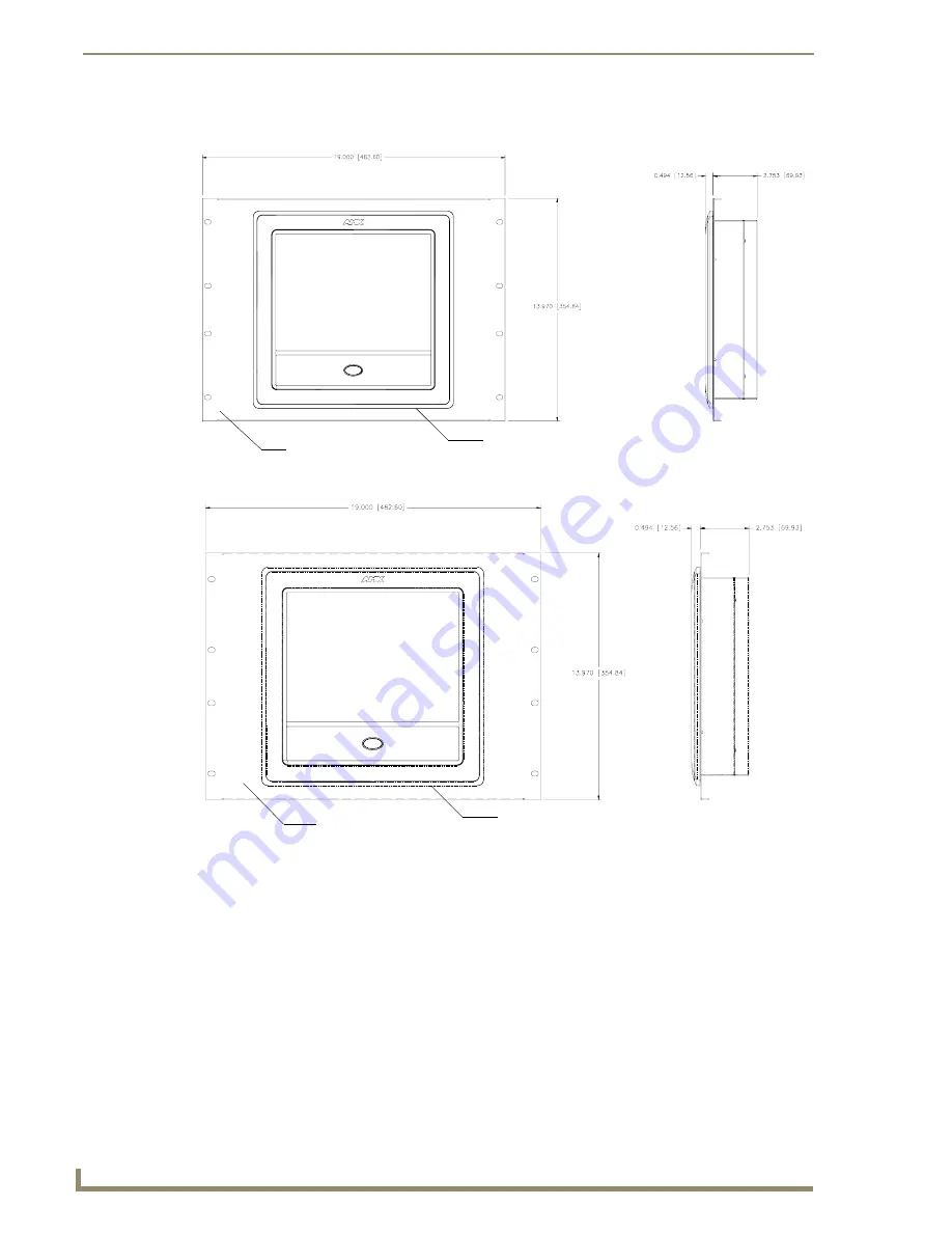
Insert the main 12-inch Modero unit into an NXA-RK12 (FIG. 46) or the 15-inch Modero into an NXA-
RK15 (FIG. 47).
7.
Secure the panel to the NXA-RK frame by first inserting and then tightening the four #4-40 screws
(provided). Line up the four mounting holes and use a grounded Phillips-head screwdriver to tighten the
screws in a clockwise direction.
8.
Insert the NXA-RK (with connected NXD unit) into the equipment rack, making sure to align the screw
holes along the sides on the NXA-RK with the holes in the equipment rack.
9.
Use a grounded Phillips-head screwdriver to secure the NXA-RK (with connected NXD unit) to the
equipment rack using #10-32 screws (not included).
10.
Place the magnet faceplate back onto the main NXD unit by gripping the faceplate and placing it on the
housing with gentle force.
Make sure to align the Microphone, Light, and PIR Motion sensor locations to
their respective openings on the front bezel/faceplate.
11.
Reconnect the terminal RJ-45, Ethernet, and any optional audio/video wiring to their respective locations
on either the NXA-AVB Breakout Box, Ethernet port, or NetLinx Master.
FIG. 46
NXD 12 inch Wall Mount panel installed into an NXA-RK12 Rack Mount Kit
FIG. 47
NXD 15 inch Wall Mount panel installed into an NXA-RK15 Rack Mount Kit
Faceplate
Rack mount
frame (NXA-RK12)
Faceplate
Rack mount frame
(NXA-RK15)


