


Black/White LCD Mini-Touch Panels
Installing the Mini-Touch Panel
9
8.
Thread the incoming AXlink and RS-232 wiring through the BB-MTP knockout.
9.
Fasten the BB-MTP to the solid surface with the mounting screws supplied with
the enclosure.
10.
Connect the AXlink and RS-232 wiring to the AXU-MLC (/PB) circuit card.
Refer to
Wiring the Mini-Touch Panel
for complete wiring information.
11.
Fasten the AXU-MLC (/PB) to the BB-MTP with the #6-32 screws provided with
the enclosure.
12.
Insert the engraved overlay back into the bezel.
13.
Connect the AXlink wiring to the AMX control system and RS-232 wiring to the
external RS-232 device. The AXU-MLC (/PB) will beep when you apply power.
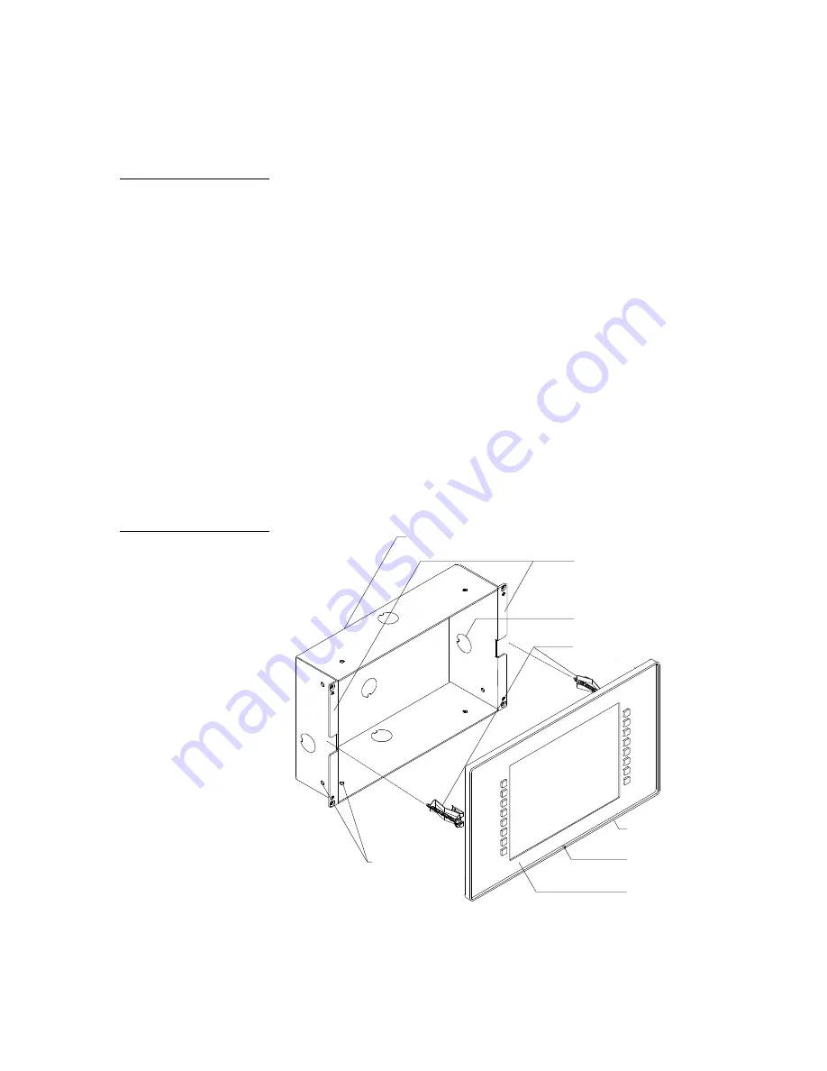
AXU-MLC (/PB) and BB-MTP (plasterboard)
Mount the AXU-MLC (/PB) and BB-MTP (Figure 8) into a plasterboard surface (or
equivalent):
Release slot
Plasterboard surface
mounting flanges
Knockout
BB-MTP UniMount enclosure
Expansion clips
Engraved overlay
Stud mounting
holes
AXU-MTP bezel
Note
The mini-touch panel must
always be installed with the
release slot located at the
bottom.
Figure 8
AXU-MLC (/PB) and BB-MTP
for plasterboard
Summary of Contents for AXM-MLC
Page 8: ...vi Table of Contents Black White LCD Mini Touch Panels ...
Page 36: ...28 Mini Touch Panel Basics Black White LCD Mini Touch Panels ...
Page 114: ...106 Mini Touch Panel Program Reference Black White LCD Mini Touch Panels ...
Page 130: ...122 Replacing the Lithium Batteries Black White LCD Mini Touch Panels ...
Page 140: ...132 Technical Support Black White LCD Mini Touch Panels ...


