Section 2 — Unit Specifications • 3
Section 2 — Unit Specifications
Purpose of the Unit
This unit has been designed and built to reduce brush
and above ground tree components into uniformed wood
chips.
General Specifications
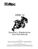
This unit is a 12
″
(30.5 cm) capacity, controlled feed drum
chipper. The chipper mechanism is permanently mounted
on the towable frame assembly. The chipper mechanism
is belt driven by a self contained engine. Material is fed
utilizing one horizontally mounted, hydraulically controlled
feed roll. Chip discharge is designed for 360 degree rota-
tion for chip body and road side discharge applications.
Item
Specification
Chipping capacity
12
″
(30.5 cm)
Engine horsepower
85 horsepower (63 kW)
Weight
5,310 pounds (2,408 kg)
Tongue weight (may vary)
530 pounds (240 kg)
Travel height
8’ 2
″
(2.5 m)
Width
6’ 8
″
(2 m)
Travel length
15’ (4.5 m)
Operational length
16’ 11
″
(5.2 m)
Feed roller opening
17
″
(43.18 cm) wide x 12
″
(30.5 cm) high
Feed table dimensions
50
″
(127 cm) wide x 30
″
(76.2 cm) deep
Infeed chute opening
50
″
(127 cm) wide x 30
″
(76.2 cm) high
Length to feed roll nip point
1
94
″
(2.4 m)
Drum dimensions
20
″
(50.8 cm) wide x 21
″
(53.3 cm) diameter
Drum weight
520 pounds (236 kg)
Drum rpm
2,230 rpm
Feed rolls
16
1
/
2
″
(41.9 cm) wide x 20
″
(50.8 cm) diameter
Feed rate
111 feet per minute (34 mpm)
Feed wheel motor rating
32.2 cu in displacement (528 cu cm)
Hydraulic pressure
2,500 psi (172.4 bar)
Hydraulic tank capacity
12 gallon (45.4 l)
Fuel tank capacity
18 gallon (68.1 l)
Discharge chute rotation
360
°
1
Measured from ground level at infeed chute, through the center of the feed table.
Figure 2.1 — Unit Specifications
Summary of Contents for DRM 12
Page 3: ......
Page 7: ...2 Section 1 Introduction...
Page 17: ...12 Section 3 Safety Rear View Top View Bottom View 12 5 22 19 10 23 10 17 30 20 3 2 30...
Page 18: ...Section 3 Safety 13 4 8 7 2 3 970116658 1 6 5...
Page 19: ...14 Section 3 Safety 970116649 970116652 12 14 13 10 11 9...
Page 21: ...16 Section 3 Safety D G G D 25 26 24 27 23 22...
Page 22: ...Section 3 Safety 17 970137595 3X 30 31 28 29...
Page 23: ...18 Section 3 Safety...
Page 41: ...36 Section 6 Care of the Unit...
Page 62: ...Appendix...
Page 63: ......
Page 79: ...16 Appendix Glossary...
Page 83: ...Appendix Daily Preoperational Checklist...
Page 85: ...Appendix Preventive Maintenance and Inspection Checklist...
Page 88: ......
Page 89: ......
Page 91: ......
Page 93: ......
Page 96: ...07 13 970413443 A 2A PAGE 1 OF 2 ASSEMBLY FEED SYSTEM HYDRAULIC LIFT DRM 12...
Page 99: ...07 13 970413407 A 3A PAGE 1 OF 4 ASSEMBLY FEED CONTROL HYDRAULIC LIFT DRM 12...
Page 103: ...08 13 970485929 A 4A PAGE 1 OF 3 ASSEMBLY HAND CRANK CHUTE ROTATION DRUM CHIPPER...
Page 108: ...07 13 970413409 A 5A PAGE 1 OF 3 ASSEMBLY POWER SYSTEM KUBOTA 67 HP 74 HP 99 HP DIESEL DRM 12...
Page 113: ...07 13 970413438 A 6A PAGE 1 OF 4 FINAL ASSEMBLY DRM 12...
Page 117: ......
Page 118: ......
Page 119: ......
Page 120: ......
Page 121: ......
Page 122: ......
Page 123: ......
Page 124: ......
Page 125: ......
Page 127: ......
Page 128: ......
Page 129: ......
Page 138: ...79A PAGE 1 OF 3 05 13 970457633 A ASSEMBLY FUEL SYSTEM DRM12 CFD1217...


