P846/EN CM/D
Commissioning
(CM) 10-10
MiCOM P846
Carefully examine the relay to see that no physical damage has occurred since installation.
Ensure that the case earthing connections, bottom left-hand corner at the rear of the relay
case, are used to connect the relay to a local earth bar using an adequate conductor.
5.1.2
Current transformer shorting contacts (optional check)
If required, the current transformer shorting contacts can be checked to ensure that they
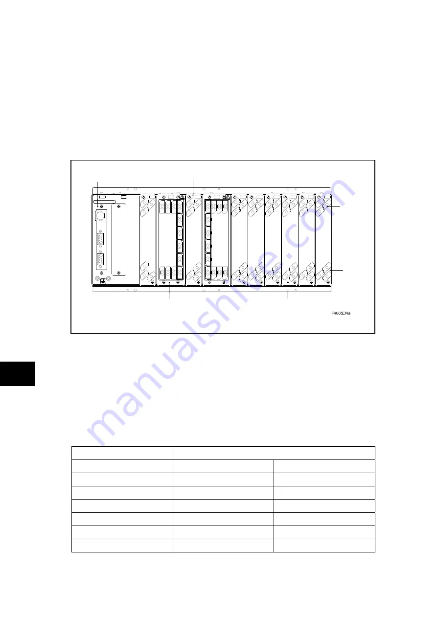
close when the heavy duty terminal block (block reference D and E in Figure 1) is
disconnected from the current input PCB.
Rear port with IRIG-B time synchronizing input which are available with the relay.
18
16
A
B
1
C
1
18
18
18
18
16
17
18
18
18
17
19
2
3
1
18
18
3
2
D
1
19
E
F
1
G
1
H
1
J
1
K
1
L
1
M
Current and Voltage
Input Terminal
Power Supply
Connection
Rear Comms
Port (EIA485)
Digital Input Connection
Digital Input Connection
IRIG-B and 2nd Rear
Comms Board
Digital Output Connection
Figure 1: Rear terminal blocks on size 80TE case (B variant)
The heavy duty terminal block is fastened to the rear panel using four crosshead screws.
These are located top and bottom between the first and second, and third and fourth,
columns of terminals (see Figure 2).
CM
Note:
The use of a magnetic bladed screwdriver is recommended to
minimize the risk of the screws being left in the terminal block or lost.
Pull the terminal block away from the rear of the case and check with a continuity tester that
all the shorting switches being used are closed. Table 1 shows the terminals between which
shorting contacts are fitted.
Current Input
Shorting Contact Between Terminals
1A CT’s
5A CT’s
IA
D3 – D2
D1 – D2
IB
D6 – D5
D4 – D5
IC
D9 - D8
D7 – D8
IA(2)
F18 – F17
F16 – F17
IB(2)
F15 – F14
F13 – F14
IC(2)
F12 – F11
F10 – F11
Table 1:
Current transformer shorting contact locations
Summary of Contents for MiCOM P846
Page 2: ......
Page 4: ......
Page 5: ...Safety Section P846 EN SS H11 SS SAFETY SECTION...
Page 6: ...P846 EN SS H11 Safety Section SS...
Page 8: ...P846 EN SS H11 Safety Section SS 2 SS...
Page 16: ...P846 EN IT D Introduction MiCOM P846 IT...
Page 18: ...P846 EN IT D Introduction IT 1 2 MiCOM P846 IT...
Page 26: ...P846 EN TD D Technical Data MiCOM P846 TD...
Page 38: ...P846 EN GS D Getting Started MiCOM P846 GS...
Page 58: ...P846 EN ST D Getting Started MiCOM P846 ST...
Page 60: ...P846 EN ST D Settings ST 4 2 MiCOM P846 ST...
Page 78: ...P846 EN OP D Operation MiCOM P846 OP...
Page 104: ...P846 EN OP D Operation OP 5 26 MiCOM P846 OP...
Page 106: ...P846 EN AP D Application Notes MiCOM P846 AP...
Page 108: ...P846 EN AP D Application Notes AP 6 2 MiCOM P846 AP...
Page 122: ...P846 EN AP D Application Notes AP 6 16 MiCOM P846 AP...
Page 124: ...P846 EN PL D Programmable Logic MiCOM P846 PL...
Page 126: ...P846 EN PL D Programmable Logic PL 7 2 MiCOM P846 PL...
Page 144: ...P846 EN MR D Measurements and Recording MiCOM P846 MR...
Page 146: ...P846 EN MR D Measurements and Recording MR 8 2 MiCOM P846 MR...
Page 160: ...P846 EN FD D Firmware Design MiCOM P846 FD...
Page 182: ...P846 EN CM D Commissioning MiCOM P846 CM...
Page 228: ...P846 EN CM D Commissioning CM 10 46 MiCOM P846 CM...
Page 230: ...P846 EN MT D Maintenance MiCOM P846 MT...
Page 232: ...P846 EN MT D Maintenance MT 11 2 MiCOM P846 MT...
Page 238: ...P846 EN TS D Troubleshooting MiCOM P846 TS...
Page 240: ...P846 EN TS D Troubleshooting TS 12 2 MiCOM P846 TS...
Page 252: ...P846 EN SC D SCADA Communications MiCOM P846 SC...
Page 272: ...P846 EN SG D Symbols and Glossary MiCOM P846 SG...
Page 280: ...P846 EN SG D Symbols and Glossary SG 14 8 MiCOM P846 SG...
Page 282: ...P846 EN IN D Installation MiCOM P846 IN...
Page 284: ...P846 EN IN D Installation IN 15 2 MiCOM P846 IN...
Page 296: ...P846 EN IN D Installation IN 15 14 MiCOM P846 IN...
Page 297: ......


