100
Rockwell Automation Publication 1560F-UM001A-EN-P - June 2019
Chapter 4
Programming
Linear Acceleration (Linear Speed) Start with Stop
Use the parameters in
Table 14
to program a Linear Acceleration Start and
Simple Stop Mode operation. You can access the Basic parameter set with the
HIM (see
Table 11
).
ATTENTION:
For Overload Protection, it is critical that you enter the data into
the SMC-50 control module as it appears on the motor nameplate.
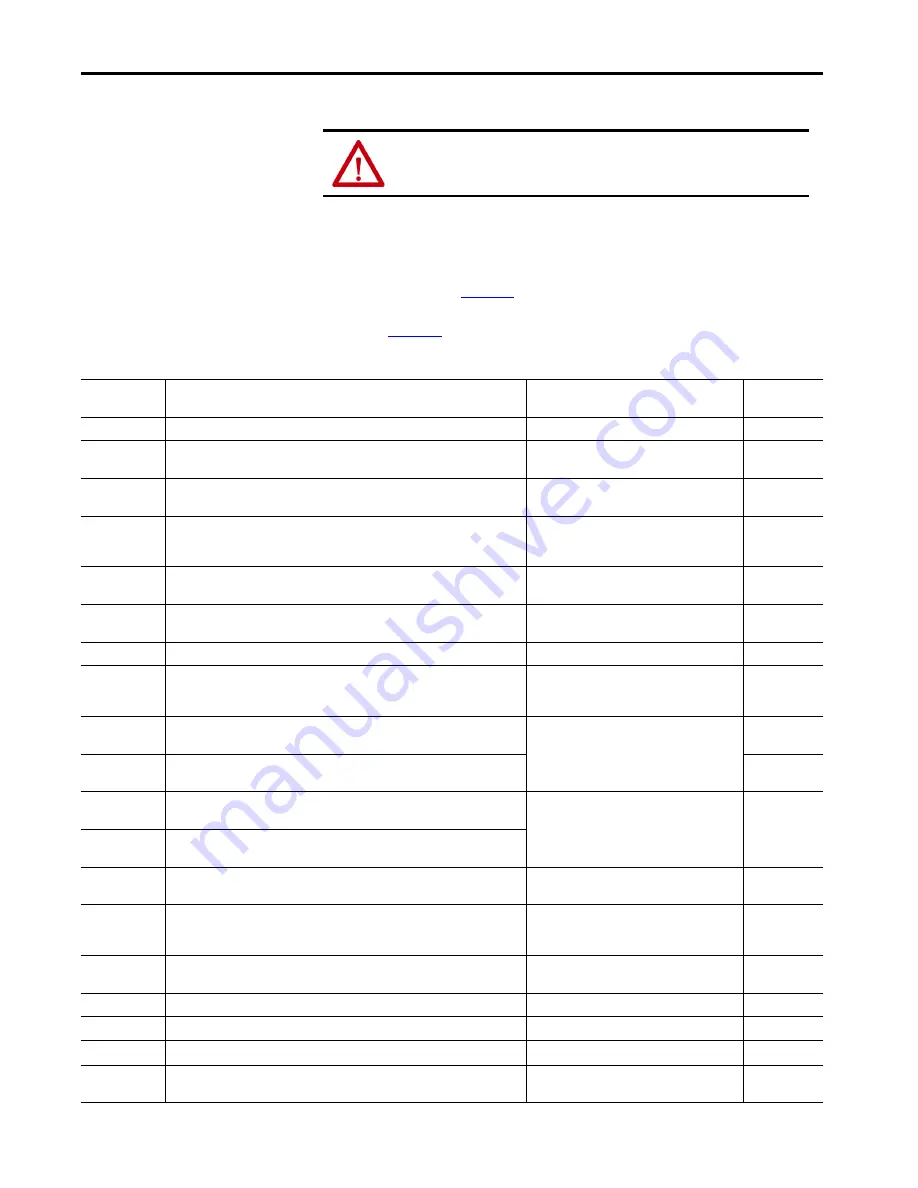
Table 14 - Linear Acceleration (Speed Sense) Start with Stop Parameters
Parameter
Name
Description
Options
Default Value
Motor Config
Setting for the motor configuration Line Connected Wye or Inside-the-Delta.
(1)
Line, Delta, Auto Detect
Auto Detect
Line Voltage
Select the value of line voltage being used in the system. The correct line voltage
value must be entered for the voltage protection functions to work properly.
0…15,000V
4160V
Starting Mode
This mode must be programmed for Linear Speed.
Linear Speed
(5)(6)
Linear
Speed
(5)(6)
Ramp Time
Programs the time period that the controller will ramp the output voltage up to full
voltage and to full speed from Stop. With the Linear Speed Starting mode, the time to
ramp to full speed closes to this value depending on load characteristics.
0…1000 s
10 seconds
Initial Torque
The initial reduced output (torque) level for the voltage ramp to the motor is
established and adjusted to this parameter. Torque level at which the ramp begins.
0…90% LRT
70% LRT
Current Limit
Level
Limits the current supplied to the motor throughout the Linear Start and Stop
cycle.
(2)
50…600% FLC
350% FLC
Stop Mode
Programs the desired Stop Mode.
(3)
Coast, Soft Stop, Linear Speed, Pump Stop
Coast
Stop Time
Programs the amount of time desired to ramp from full to zero voltage for Soft,
Linear, and Pump Stop mode. Actual ramp stop time depends on the stopping mode
selected and load inertia.
0…999 s
0 s
Input 1
Programs the desired operation of the Control Module to a change in status of Input
#1 wired to control terminal #11 (24V DC).
Disable, Start, Coast, Stop Option, Start/Coast,
Start/Stop, Dual Ramp, OL Select, Fault, Fault NC,
Clear Fault, Emerg Run
Start/Coast
Input 2
Programs the desired operation of the Control Module to a change in status of Input
#2 wired to control terminal #10 (24V DC).
Disable
Aux 1 Config
Programs the control function of the Auxiliary Output Contact #1, wired across
control terminal #4 and #5.
(4)
Normal, UTS, Fault, Alarm, Ext Bypass, Ext Brake,
Aux Control
(7)
, Network 1, Network 2, Network 3,
Network 4, Fan Control
Normal
Aux 2 Config
Programs the control function of the Auxiliary Output Contact #2, wired across
control terminal #6 and #7.
(4)
Overload Class
Required for motor protection. Lets you select the time-to-trip for the built-in Motor
Overload. This selection is based on the type of motor being used and the application.
5…30
10
Service Factor
Required for motor protection. This programmed value is taken directly from the
nameplate and used by the controller to determine the ultimate Overload Trip
Current.
0.01…1.99
1.15
Motor FLC
Required for motor protection. This programmed value is taken directly from the
motor nameplate.
1.0…2200.0 A
1.0 Amps
Starting Torque
NOT used for a Linear Speed Start.
0…300% RMT
100 RMT
Max Torque
NOT used for a Linear Speed Start.
0…300% RMT
250% RMT
Rated Torque
NOT used for a Linear Speed Start.
0…100,000 N·m
10 N·m
Rated Speed
NOT used for a Linear Speed Start.
750, 900, 1000, 1200, 1500, 1800, 3500,
3600 rpm
1800 rpm
Summary of Contents for SMC-50
Page 10: ...10 Rockwell Automation Publication 1560F UM001A EN P June 2019 Table of Contents Notes ...
Page 12: ...12 Rockwell Automation Publication 1560F UM001A EN P June 2019 Preface Notes ...
Page 68: ...68 Rockwell Automation Publication 1560F UM001A EN P June 2019 Chapter 2 Installation Notes ...
Page 120: ...120 Rockwell Automation Publication 1560F UM001A EN P June 2019 Chapter 4 Programming Notes ...
Page 130: ...130 Rockwell Automation Publication 1560F UM001A EN P June 2019 Chapter 5 Metering Notes ...
Page 156: ...156 Rockwell Automation Publication 1560F UM001A EN P June 2019 Chapter 8 Diagnostics Notes ...
Page 198: ...198 Rockwell Automation Publication 1560F UM001A EN P June 2019 Chapter 10 Maintenance Notes ...
Page 284: ...284 Rockwell Automation Publication 1560F UM001A EN P June 2019 Appendix H Spare Parts Notes ...
Page 286: ...286 Rockwell Automation Publication 1560F UM001A EN P June 2019 Appendix I Accessories Notes ...
Page 291: ......


