


Triggering the Oscilloscope
4
6000 Series Oscilloscope User’s Guide
189
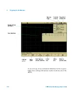
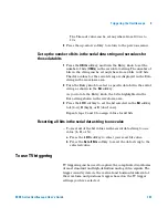
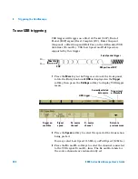
The selected trigger source is displayed in the upper-right
corner of the display. Turning the Trigger
Level
knob does not
change the trigger level because the trigger level is
automatically set to the sync pulse. Trigger coupling is
automatically set to
TV
in the Trigger
Mode/Coupling
menu.
3
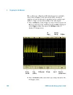
Press the sync polarity softkey to set the TV trigger to either
positive (
) or negative (
) sync polarity.
4
Press the
Standard
softkey to set the TV standard.
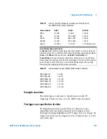
The oscilloscope supports triggering on the following
television (TV) and video standards.
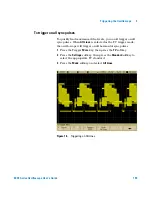
5
Press the
Mode
softkey to select the portion of the video
signal that you would like to trigger on.
The TV trigger modes available are:
•
Field1
and
Field2
— Trigger on the rising edge of the first
serration pulse of field 1 or field 2 (interlaced standards
only).
•
All Fields
— Trigger on the rising edge of the first pulse in
the vertical sync interval (not available in Generic mode).
•
All Lines
— Trigger on all horizontal sync pulses.
Provide Correct Matching
Many TV signals are produced from 75
Ω
sources. To provide correct matching to
these sources, a 75
Ω
terminator (such as an Agilent 11094B) should be
connected to the oscilloscope input.
Standard
Type
Sync Pulse
NTSC
Interlaced
Bi-level
PAL
Interlaced
Bi-level
PAL-M
Interlaced
Bi-level
SECAM
Interlaced
Bi-level
Generic
Interlaced/Progressive
Bi-level/Tri-level
EDTV 480p/60
Progressive
Bi-level
HDTV 720p/60
Progressive
Tri-level
HDTV 1080p/24
Progressive
Tri-level
HDTV 1080p/25
Progressive
Tri-level
HDTV 1080i/50
Interlaced
Tri-level
HDTV 1080i/60
Interlaced
Tri-level
Summary of Contents for InfiniiVision 6000 Series
Page 1: ...Agilent Technologies Agilent InfiniiVision 6000 Series Oscilloscopes User s Guide ...
Page 60: ...60 6000 Series Oscilloscope User s Guide 1 Getting Started ...
Page 126: ...126 6000 Series Oscilloscope User s Guide 3 Viewing and Measuring Digital Signals ...
Page 292: ...292 6000 Series Oscilloscope User s Guide 6 Displaying Data Interpreting Decoded LIN Data ...
Page 314: ...314 6000 Series Oscilloscope User s Guide 6 Displaying Data ...
Page 354: ...354 6000 Series Oscilloscope User s Guide 8 Reference ...
Page 362: ...362 6000 Series Oscilloscope User s Guide 9 ...