


184
6000 Series Oscilloscope User’s Guide
4
Triggering the Oscilloscope
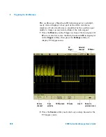
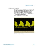
Assign source channels to the clock, data, and frame signals
1
Press the
Signals
softkey to access SPI trigger settings for
clock source and slope, data source, and frame type and
source.
2
Press the
Clock
softkey or turn the Entry knob to select the
channel connected to the SPI serial clock line.
As you press the
Clock
softkey (or rotate the Entry knob on
mixed-signal oscilloscopes), the
CLK
label for the source
channel is automatically set and the channel you select is
shown in the upper-right corner of the display next to “
SPI
”.
Adjust the trigger level for the selected analog channel by
turning the Trigger Level knob. Press the
D15 Thru D0
key and
select
Thresholds
to set the threshold level for digital
channels. The value of the trigger level or digital threshold is
displayed in the upper-right corner of the display.
3
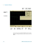
Press the slope softkey (
) to select rising edge or falling
edge for the selected Clock source.
This determines which clock edge the oscilloscope will use to
latch the serial data. When you press the slope softkey, the
graphic shown on the display changes to show the current
state of the clock signal.
Clock
channel
Clock
slope
Data
channel
Frame
channel
Return to
previous menu
Frame by
condition
Summary of Contents for InfiniiVision 6000 Series
Page 1: ...Agilent Technologies Agilent InfiniiVision 6000 Series Oscilloscopes User s Guide ...
Page 60: ...60 6000 Series Oscilloscope User s Guide 1 Getting Started ...
Page 126: ...126 6000 Series Oscilloscope User s Guide 3 Viewing and Measuring Digital Signals ...
Page 292: ...292 6000 Series Oscilloscope User s Guide 6 Displaying Data Interpreting Decoded LIN Data ...
Page 314: ...314 6000 Series Oscilloscope User s Guide 6 Displaying Data ...
Page 354: ...354 6000 Series Oscilloscope User s Guide 8 Reference ...
Page 362: ...362 6000 Series Oscilloscope User s Guide 9 ...