


Triggering the Oscilloscope
4
6000 Series Oscilloscope User’s Guide
185
4
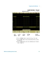
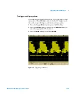
Press the
Data
softkey or turn the Entry knob to select the
channel that is connected to the SPI serial data line. (If the
channel you selected is off, switch it on.)
As you press the
Data
softkey (or rotate the Entry knob on
mixed-signal oscilloscopes), the
DATA
label for the source
channel is automatically set and the channel you select is
shown in the upper-right corner of the display next to “
SPI
”.
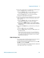
Adjust the trigger level for the selected analog channel by
turning the Trigger Level knob. Press the
D15 Thru D0
key and
select
Thresholds
to set the threshold level for digital
channels. The value of the trigger level or digital threshold is
displayed in the upper-right corner of the display.
5
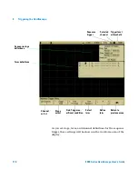
Press the
Frame by
softkey to select a framing signal that the
oscilloscope will use for determining which clock edge is the
first clock edge in the serial stream.
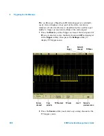
Graphic showing
current state of SPI
trigger clock slope and
chip select polarity or
timeout selection
Labels automatically
set for clock, data,
and chip select
signals
Summary of Contents for InfiniiVision 6000 Series
Page 1: ...Agilent Technologies Agilent InfiniiVision 6000 Series Oscilloscopes User s Guide ...
Page 60: ...60 6000 Series Oscilloscope User s Guide 1 Getting Started ...
Page 126: ...126 6000 Series Oscilloscope User s Guide 3 Viewing and Measuring Digital Signals ...
Page 292: ...292 6000 Series Oscilloscope User s Guide 6 Displaying Data Interpreting Decoded LIN Data ...
Page 314: ...314 6000 Series Oscilloscope User s Guide 6 Displaying Data ...
Page 354: ...354 6000 Series Oscilloscope User s Guide 8 Reference ...
Page 362: ...362 6000 Series Oscilloscope User s Guide 9 ...