


3-22
Programming
Monitoring the Instrument
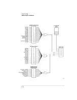
Queues
There are two queues in the instrument: the output queue and the
error queue. The values in the outp ut queue and the error queue can
be queried.
Output queue
The output queue stores the instrument responses that are generated
by certain commands and queries that you send to the instrument. The
outp ut queue generates the Message Available summary bit when the
output queue contains one or more bytes. This summary bit sets the
MAV bit (bit 4) in the Status Byte Register. The method used to read
the Outp ut Queue dep ends up on the p rogramming language and envi-
ronment. For examp le, with HP BASIC, the outp ut queue may be read
using the ENTER statement.
Error queue
As errors are detected, they are p laced in an error queue. Instrument
specific errors are indicated by positive values. General errors have
negative values. You can clear the error queue by reading its contents,
sending the *CLS command, or by cycling the instrument’s power.
The error queue is first in, first out. If the error queue overflows, the
last error in the queue is rep laced with error - 350, “Queue overflow.”
Any time the queue overflows, the least recent errors remain in the
queue, and the most recent error is discarded. The length of the
instrument’s error queue is 30 (29 p ositions for the error messages,
and 1 position for the “Queue overflow” message).
The error queue is read with the SYSTEM:ERROR? query. Executing
this query reads and removes the oldest error from the head of the
queue, which op ens a p osition at the tail of the queue for a new error.
When all the errors have been read from the queue, subsequent error
queries return 0, “No error.”
For more information on reading the error queue, refer to
“ERRor” on
page 4- 98
. For a list of errors messages,
refer to “Error Messages” on
page 7- 11
.
Summary of Contents for 86120C
Page 12: ......
Page 26: ...1 14 Getting Started Returning the Instrument for Service ...
Page 27: ...1 15 Getting Started Returning the Instrument for Service ...
Page 28: ......
Page 96: ...3 18 Programming Monitoring the Instrument ...
Page 128: ...3 50 Programming Lists of Commands ...
Page 236: ...4 108 Programming Commands UNIT Subsystem ...
Page 248: ......
Page 264: ...6 16 Specifications and Regulatory Information Product Overview ...
Page 269: ...7 5 Reference Menu Maps Appl s Menu ...
Page 271: ...7 7 Reference Menu Maps Display List by WL Menu Delta On Menu ...
Page 273: ...7 9 Reference Menu Maps System Print Menu ...
Page 274: ...7 10 Reference Menu Maps System Setup Menu ...
Page 284: ......
Page 292: ......
Page 293: ......


