Release: 02.0
2017-01-13
Page 45
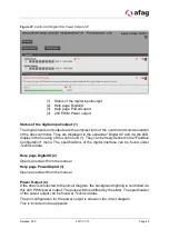
Figure 37: Control Unit Digital IO & Power Output 24V
(1) Status of the digital input/output
(2) Help page DigitalIO
(3) Help page PowerOuptut
(4) 24V PWM Power output
Status of the digital input/output (1)
The digital inputs and outputs are the simplest form of the control and communication
of the aflex controller. They are displayed in the expander "Digital IO" and via the LED
display in the housing of the control unit (1). They can be freely defined in the "Fieldbus
Configuration" menu. The specifications of the digital interface can be found under
Help page DigitalIO (2)
Opens an extract from the manual
Help page PowerOuptut (3)
Opens an extract from the manual
Power Output (4)
If the aflex is connected to the circuit diagram, the background lighting is controlled via
this 24V PWM power output. The pulse width is defined by the slider. The specification
of the power output can be found at
The pin configuration for the power output is shown in the circuit diagram.
This is included in the appendix.
1
2
4
3


