Installation
60/ 122
Powerlift prefabricated pumping station
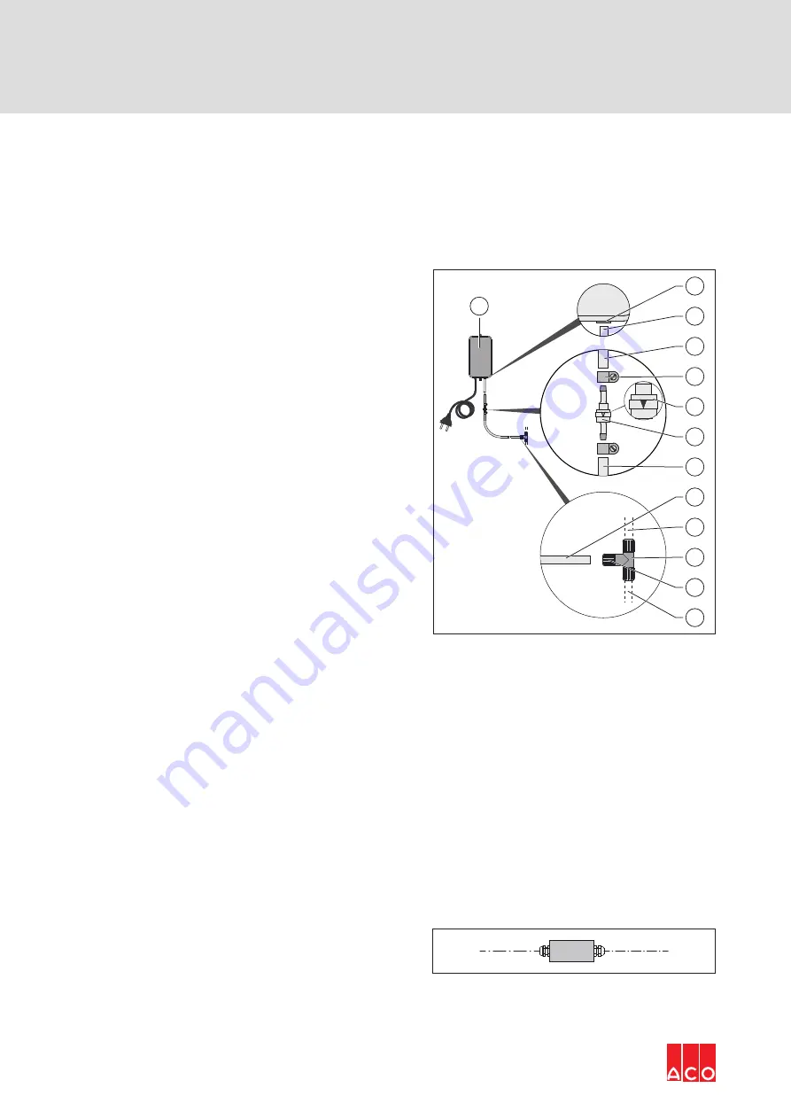
Connecting the control pipe
In the as-delivered condition, the connection parts are enclosed with the mini compressor as
loose items.
IMPORTANT
In order to prevent malfunctions:
Utilise a cutting knife to adjust the control pipe length at right angles.
Î
Cut the control pipe (12).
Î
Push the hose ends (8, 9 + 12) into the
retainers of the screw-in T-fitting (10)
and clamp (tighten hand-tight) using the
respective union nuts (11).
Î
Push hose clamp (4) over the end (7) of
the 0.5 m long hose.
Î
Push the hose end (7) onto the hose
bush of the spring check valve (6), in
accordance with the installation direction
(5), and fix using a hose clamp (4).
Î
Push hose clamp (4) over the end (3) of
the 0.5 m long hose.
Î
Push the hose end (3) onto the other
hose bush of the spring check valve (6)
and fix using a hose clamp (4).
Î
Push the other end of the hose (2) over
the retainer (1) of the mini compressor
(13).
13
2
1
3
4
5
6
7
8
9
10
11
12
3.5.10 Connecting the malfunction or fault signalling
equipment (optional)
If malfunction or fault signalling equipment is specified, then this should be installed in such a
way that a malfunction is signalled to each connected unit.
A suitable, on-site cable must be connected in the control to forward the potential-free contact
as a group alarm. Optional for on-site GLT signal output cable as NYY-J or NYM-J 12 x 0.75 mm²
for potential-free, interchangeable contact / contact load 230 V AC / 3A.
3.5.11 Installing ex-barrier
IMPORTANT
If the level probe is to be utilised in an explosion protected area, then an
ex-barrier must be installed.
Î
Ex-barrier must be installed and/or
connected in the connection cable for
the level probe.


