


61
CO M M U N I C AT I O N B OA R DS
—
Communication boards
11
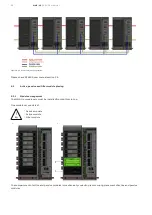
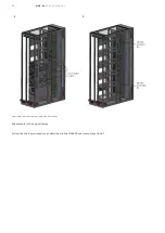
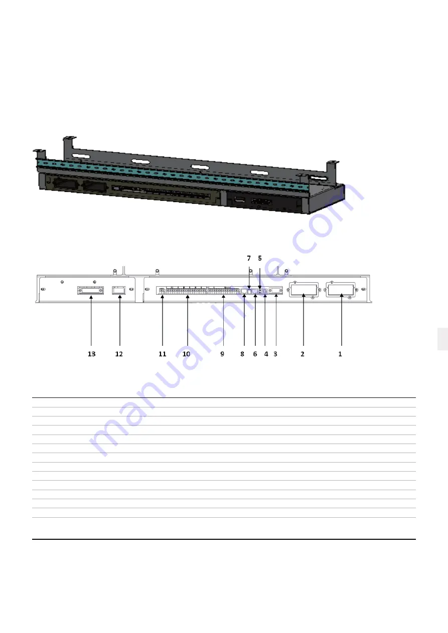
The communication boards are located below the control wiring duct in the MNS-Up module.
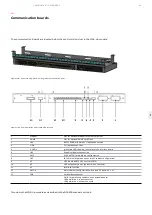
Figure 11-01 Control wiring duct with integrated communication ports
Figure 11-02 Communication ports in MNS-Up systems
1
Modem
Slot for optional Modem/Ethernet card ONLY
2
SNMP
Slot for optional SNMP card ONLY
3
JD1
RS232 Sub D9/female PC / laptop connection
4
USB
PC/laptop connection
5
2 LED’s
green/red LED showing the status of the interface board
6
JR3
Graphical display connection
7
SW2
DIP-SWITCH for multidrop configuration
8
JR2
(RJ 45) multidrop connection (multi-cabinet configuration)
9
X3
UPS inputs and 12VDC source (X3 5/6)
10
X2
UPS outputs dry ports (potential free contacts)
11
X1
Interlock function
12
SW1-9
Multi-cabinet configuration switch (see 5.1.6 and 6.1.2.4)
13
JD8
Parallel bus connector
ONLY for paralleling cabinets, use optional adapter:
JD5 parallel bus - input connector
JD6 parallel bus - output connecto
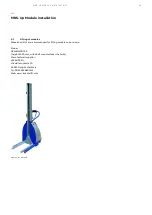
Turn down the MNS-Up module as described in the DPA500 manual section 5.
Summary of Contents for MNS-Up
Page 6: ... 01 Introduction ...
Page 8: ... 02 Safety first ...
Page 12: ... 03 General technical data ...
Page 16: ... 04 System description ...
Page 18: ... 05 Packing storage and transportation ...
Page 36: ... 06 Transport ...
Page 40: ... 07 Erecting ...
Page 47: ...47 ERECTING ...
Page 48: ... 08 MNS Up configuration ...
Page 52: ... 09 MNS Up Module installation ...
Page 55: ...55 MNS UP MODULE INSTALL ATION ...
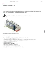
Page 56: ... 10 Handling of EMC boards ...
Page 59: ...59 HANDLING OF EMC BOARDS ...
Page 60: ... 11 Communication boards ...
Page 62: ... 12 MNS 3 0 sections ...
Page 64: ... 13 Commissioning ...
Page 66: ... 14 Operating of MNS Up system ...
Page 68: ... 15 Tightening torques for screw connection in MNS Up ...
Page 72: ... 16 Spare parts ...
Page 74: ... 17 Onsite inspection and maintenance ...
Page 76: ... 18 Maintenance intervals ...
Page 81: ...81 MAINTENANCE INTERVALS ...
Page 83: ......


