Beckhoff EP9224-0037, Documentation
The Beckhoff EP9224-0037 product includes comprehensive documentation for easy installation and operation. You can download the user manual for free on our website. Ensure successful setup by accessing the detailed manual at manualshive.com. Perfect for ensuring a smooth experience with this innovative product.
Share
Download


Reviews:
No comments
Related manuals for EP9224-0037

AP21000uk3M
Brand: Belkin Pages: 28

PDU-UK-6
Brand: Penn Elcom Pages: 3

GEK-45404F
Brand: GE Pages: 32

GEK-106465A
Brand: GE Pages: 43
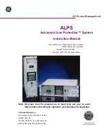
ALPS
Brand: GE Pages: 366

745 TRANSFORMER MANAGEMENT RELAY
Brand: GE Pages: 408

D90 Plus
Brand: GE Pages: 694

PDUMH15HVNET
Brand: Tripp Lite Pages: 4

?TIGW150/230 V
Brand: MAC TOOLS Pages: 28

UNI
Brand: PANCONNECT Pages: 3

SPM
Brand: GE Pages: 126

AUX1NO+1NCDMM
Brand: Eaton Pages: 2

Powerware 225 kVA Three-Phase Power Distribution Unit
Brand: Eaton Pages: 142

965 Five-Station
Brand: Teledyne Pages: 22

WA405
Brand: Shure Pages: 22

SP-EVCP-R
Brand: Matt:e Pages: 10

IP-EVCP-M
Brand: Matt:e Pages: 17

16199
Brand: Lorell Pages: 13


