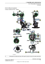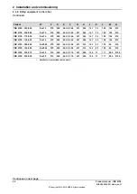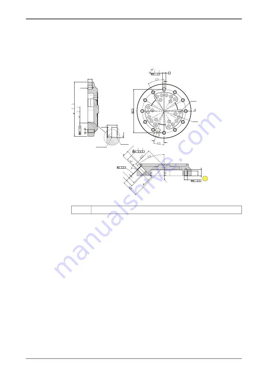
Tool flange, standard
Below is the standard tool flange. The guide pin hole is, in calibration position,
pointing upwards in Z-direction.
22
101
12
3x R 0,8 -0,4
+2
3x R 0,8 0
+1
1x45
45°
2,5
A
11x M12
18 H7
+
0,018
0
28
+
2
0
25 min. (H7)
30°
17,4 min.
1
45°
24
+
2
0
(Counterbore)
68,5
61
18 min.
23 max.
B-B
C
L C-D
1,6
0,2 A
B
0,3 C D
0,2 C D
B
12 H7
0
+0,018
6x R11
3x R70
160
11x
30°
18°
A
A
B
B
0,04 A
B
1,6
16 ±1
0,5
45°
X
M
12
A-A
200
h8
-
0,072
0
100
H7
0
+
0,035
0,02
A
xx1300000280
Thread length: 18 mm.
A
The turning disc for robot variants IRB 6700 - 200/2.60 and IRB 6700 - 155/2.85
was redesigned when Axis Calibration was introduced for IRB 6700. Prior to Axis
Calibration the holes on the disc were through. On the current turning disc the
holes are not through.
Fastener quality
Use suitable screws and tightening torque for your application, screws with quality
class 12.9 are recommended.
Continues on next page
94
Product manual - IRB 6700
3HAC044266-001 Revision: N
© Copyright 2013 - 2018 ABB. All rights reserved.
2 Installation and commissioning
2.4.8 Fitting equipment to the robot
Continued
Summary of Contents for IRB 6700 Series
Page 1: ...ROBOTICS Product manual IRB 6700 ...
Page 46: ...This page is intentionally left blank ...
Page 110: ...This page is intentionally left blank ...
Page 786: ...This page is intentionally left blank ...
Page 812: ...This page is intentionally left blank ...
Page 836: ...This page is intentionally left blank ...
Page 838: ...This page is intentionally left blank ...
Page 845: ......


