ABB FEX300 Operating	 Instruction Download Page 103

 Parameterization


OI/FEX300/FEX500-EN FEX300, 

FEX500 

103 


7.4.5  Menu: Input / Output 
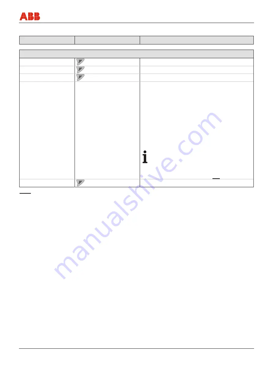
 

Menu / Parameter 

Value range 

Description 


Input/Output 


Digital Out Mode 


Select the "Digital Output Mode" submenu. 

Logic Setup 


Select the "Logic Setup" submenu. 

Pulse Setup 


Select the "Pulse Setup" submenu. 

Digital Input Setup 

No Function, Totalizer 
Reset(All), Flowrate to Zero, 
System Zero Adjust, Totalizer 
Stop(All), Dual Range, 
Start/Stop Batching 1) 

Select the operating mode for the digital output. There 
are four operating modes available: 
•  Totalizer reset for all totalizers (forward, reverse 

and differential totalizers) 

•  Ext. zero return 
•  External adjustment of zero point 
•  External totalizer stop for all totalizers (forward, 

reverse and differential totalizers). 

•  Switchover between flow ranges 1 and 2 (Qmax 

and Qmax 2) 

•  Start / stop of the fill function (batch) 

1)

.  

Default setting: external switch-off 


Important (Notice) 

If the fill operation is stopped before the 
configured fill quantity is reached, the fill totalizer 
is set to zero. When the fill function is restarted, 
the interrupted fill operation is 

not

 continued. 

Current Output 


Select the "Current Output" submenu. 

italics 

= Parameter can only be viewed at the "Advanced" password level. 

1)  Parameter / menu only available for FEP500 / FEH500. 


Summary of Contents for FEX300

Page 1: ...erating Instruction OI FEX300 FEX500 EN Electromagnetic Flowmeter ProcessMaster HygienicMaster FEX300 FEX500 Valid from software version 01 01 00 for HART 00 01 00 for PROFIBUS PA or FOUNDATION Fieldb...

Page 2: ...on service de abb com ABB Inc 125 E County Line Road Warminster PA 18974 USA Phone 1 215 674 6000 Fax 1 215 674 7183 Flow us abb com ABB Engineering Shanghai Ltd No 5 Lane 369 Chuangye Road Kangqiao T...

Page 3: ...ice designs 18 2 2 1 Design 19 2 2 2 Model with compact design 19 2 2 3 Model with remount mount design 19 3 Transport and storage 20 3 1 Inspection 20 3 2 Transport of flanged units smaller than DN 4...

Page 4: ...class IP 68 43 5 3 Connecting the transmitter 45 5 3 1 Connecting the supply power 45 5 3 2 Transmitter 46 5 3 3 Devices with HART protocol 47 5 3 4 Devices with PROFIBUS PA or FOUNDATION Fieldbus 48...

Page 5: ...erprint 132 8 1 9 Checking the grounding 132 8 2 Checking the grounding 133 8 2 1 Performing the grounding check 133 8 3 Recommended settings for diagnostic limit values 135 8 3 1 Limit values for the...

Page 6: ...according to EN 60529 159 13 1 2 Pipeline vibration according to EN 60068 2 6 159 13 1 3 Installation length 159 13 1 4 Signal cable for external transmitters only 159 13 1 5 Temperature range 159 13...

Page 7: ...has been tested and left the factory in perfect working order from a safety perspective The information in the manual must be observed and followed in order to maintain this state throughout the peri...

Page 8: ...g on parts Removing material e g by spot drilling the housing 1 4 Target groups and qualifications Installation commissioning and maintenance of the product may only be performed by trained specialist...

Page 9: ...tion may result in death or severe injury WARNING Bodily injury This symbol in conjunction with the signal word Warning indicates a potential electrical hazard Failure to observe this safety informati...

Page 10: ...Year of manufacture 13 CE mark 14 Serial number for identification by the manufacturer 15 Supplementary information EE grounding electrodes TFE partial filling electrode 16 Accuracy to which the unit...

Page 11: ...FE partial filling electrode 14 Accuracy to which the unit was calibrated e g 0 2 of rate 15 Excitation frequency of sensor coils 16 Label indicating whether the unit is subject to the Pressure Equipm...

Page 12: ...e detailed information about the technical design refer to the data sheet or the order confirmation 2 Order no 3 Client specific TAG number if specified 4 Tamb maximum permissible ambient temperature...

Page 13: ...tions 1 9 Safety instructions for electrical installation Electrical connections may only be established by authorized specialist personnel in accordance with the electrical circuit diagrams The elect...

Page 14: ...imit values The device is designed for use exclusively within the stated values on the name plate and within the technical limit values specified in the data sheets The following technical limit value...

Page 15: ...lity check the following items through a regular inspection the pressure carrying walls lining of the pressure device the measurement related function the leak tightness the wear corrosion 1 14 Return...

Page 16: ...ection points According to the WEEE Directive 2002 96 EC only products used in private applications may be disposed of at municipal garbage facilities Proper disposal prevents negative effects on peop...

Page 17: ...UE is proportional to the magnetic induction B the electrode spacing D and the average flow velocity v Considering that the magnetic induction B and the electrode spacing D are constant values a propo...

Page 18: ...suring accuracy 0 4 optional 0 2 of rate X X Measuring accuracy 0 3 optional 0 2 of rate X X Batch functions Presetting counter overrun correction external start stop batch end contact X X Other softw...

Page 19: ...ter sensor form a single mechanical entity ProcessMaster HygienicMaster Fig 5 2 2 3 Model with remount mount design The transmitter is mounted in a separate location from the flowmeter sensor The elec...

Page 20: ...n 3 2 Transport of flanged units smaller than DN 450 Warning Danger of injuries due to slipping meter The center of gravity for the complete device may be higher than the lifting straps Make sure the...

Page 21: ...lifted at the middle of the housing when transporting via forklift Flanged units may not be lifted by the terminal box or at the middle of the housing Use only the eye bolts on the device to lift and...

Page 22: ...ossible turbulence could influence the device accuracy The pipeline may not exert excessive forces or torques on the device Do not remove the plugs in the cable connectors until you are ready to insta...

Page 23: ...ht and left of the measuring tube To prevent possible leakage make sure that the liner on the flange is not cut or damaged 2 Position the measuring tube coplanar and centered between the pipes 3 Insta...

Page 24: ...7 14 68 14 68 PN40 9 78 7 27 20 75 20 75 PN63 100 24 57 20 42 42 15 42 15 CL150 5 29 5 29 18 49 18 49 CL300 9 77 9 77 33 28 33 28 CL600 15 99 15 99 20 3 4 JIS 10K 4 1 1 88 20 75 20 75 PN40 13 32 8 6 1...

Page 25: ...19 46 104 6 104 6 CL300 75 54 26 91 75 54 75 54 CL600 84 63 84 63 80 3 JIS 10K 16 26 9 65 45 07 47 16 PN16 20 7 12 22 49 68 78 19 PN40 67 77 47 12 78 24 78 19 PN63 107 4 95 79 148 5 119 2 CL150 17 41...

Page 26: ...226 9 167 9 CL150 144 8 83 9 270 5 263 350 14 CL300 424 1 252 7 463 9 259 4 PN10 108 2 75 61 120 1 113 9 PN16 189 137 2 191 4 153 8 PN25 399 4 366 404 246 7 CL150 177 6 100 229 3 222 8 400 16 CL300 53...

Page 27: ...request On request PN10 541 3 419 2 On request On request PN16 955 5 756 1 On request On request PN25 2006 1612 On request On request CL150 654 2 598 8 650 6 385 1 1000 40 CL300 2181 On request On re...

Page 28: ...0 EN 4 2 2 Variable process connections HygienicMaster Meter size DN Max tightening torque mm inch Nm 1 2 1 25 3 32 PVC POM 0 2 Brass 1 4571 3 3 10 3 8 8 15 1 2 10 20 3 4 21 25 1 31 32 1 1 4 60 40 1 1...

Page 29: ...er Hygienic Process connections to use with hygienic components and equipment All weld stub combinations provided by ABB are approved The threaded pipe connection conforming to DIN11851 is approved wh...

Page 30: ...pe section 2 For compliance with the measuring accuracy observe the inlet and outlet pipe sections G00037 1 2 3xDN 2xDN Fig 15 4 5 3 Vertical connections Vertical installation for measurement of abras...

Page 31: ...th extended diagnostic functions For devices with extended diagnostic functions different installation conditions may be valid For further information read and observe chapter 8 Extended diagnostic fu...

Page 32: ...l connecting cables must be switched off 1 Switch off supply power 2 Unscrew housing cover 1 3 Pull back the anti rotation lock 2 and turn the display 90 to the left or right until the lock 2 catches...

Page 33: ...ls in the station ground and in the pipeline should be identical An additional ground on the terminals is not required Important Notice If the flowmeter sensor is installed in plastic or earthenware p...

Page 34: ...the threaded nuts M6 1 to the pipeline and connect the ground as shown in the illustration 2 Use a copper wire at least 2 5 mm 14 AWG to establish the ground connection between the sensor 2 and an app...

Page 35: ...installed in the device option If grounding electrodes are used the grounding plate is not necessary 1 Install the flowmeter sensor with grounding plate 3 in the pipeline 2 Connect the terminal lug 2...

Page 36: ...they function as a grounding plate For plastic or pipes with insulating lining electrically connect the protective plate in the same manner as a grounding plate 4 7 7 Ground with conductive PTFE groun...

Page 37: ...ig 29 Fig 30 If the occurrence of external stray currents is to be expected in pipelines with internal insulation e g in the case of long pipe sections in the vicinity of power supply units an uninsul...

Page 38: ...s 4 7 9 2 Mixed system pipeline with CCP and functional ground potentials This mixed system has an insulated pipeline with CCP potential and an uninsulated bar metal pipe L 1 4 x flowmeter sensor size...

Page 39: ...m2 AWG 20 for all other wires The shields may not touch signal short circuit Fig 32 Flowmeter sensor side dimensions in mm inch Fig 33 Transmitter side dimensions in mm inch L1 maximum stripped length...

Page 40: ...1030 70 2 76 1 2 3 4 5 6 7 8 9 11 10 X 8 0 31 25 0 98 X Fig 34 Flowmeter sensor side dimensions in mm inch G01031 X L2 1 2 3 4 5 6 7 8 9 10 11 8 0 31 25 0 98 X Fig 35 Transmitter side dimensions in mm...

Page 41: ...d 200 m 656 ft with pre amplifier Avoid routing the cable in the vicinity of electrical equipment or switching elements that can create stray fields switching pulses and induction If this is not possi...

Page 42: ...FEH525 Connections can only be made with the supply power switched off The unit must be grounded The sensor is connected to the transmitter via the signal magnet coil cable part no D173D027U01 or D173...

Page 43: ...connect the sensor and the transmitter 2 Connect the cable in the terminal box of the sensor 3 Route the cable from the terminal box to above the maximum flooding height of 5 m 16 4 ft 4 Tighten the...

Page 44: ...parations Preparation Complete the installation before beginning sealing activities in order avoid moisture penetration Before starting check all the connections for correct fitting and stability Do n...

Page 45: ...and must be dimensioned in accordance with the current consumption of the flowmeter measuring system The leads must comply with IEC 227 and or IEC 245 The circuit breaker should be located near the tr...

Page 46: ...tion as a driven shield to transmit the measurement signal The cable is attached to the sensor and transmitter according to the connection diagram Fig 41 1 Terminal cover 2 Busbar SE 3 Clip 4 Signal a...

Page 47: ...ng software Factory setting is Pulse Output The output can be configured as an active or passive output Configuration is performed using software Configuration as pulse output Max pulse frequency 5250...

Page 48: ...against polarity reversal The bus address can be set via the DIP switches in the device the transmitter display or the fieldbus or FOUNDATION Fieldbus in acc with IEC 61158 2 FF FF U 9 32 v I 10 mA no...

Page 49: ...300 350 400 450 500 550 600 650 700 17 18 19 20 21 22 23 24 25 26 27 28 29 30 U V 2 R B Fig 44 Digital output DO1 Max permissible load RB as a function of the source voltage U2 A Active configuration...

Page 50: ...nd FOUNDATION Fieldbus G00248 2 FF FF R C 1 97 PA R C PA 98 97 98 I E I E The resistance R and condenser C form the bus termination They must be installed when the device is connected to the end of th...

Page 51: ...no 0x3430 Alternative standard ID no 0x9700 or 0x9740 Configuration Directly on the device Software DAT200 Asset Vision Basic PROFIBUS PA DTM Transmission signal Acc to IEC 61158 2 Cable Shielded twi...

Page 52: ...nction Fault Disconnection Electronic integrated in the device is ensures that the current consumption can rise to a maximum of 13 mA Upper current limit electronically restricted The voltage on the b...

Page 53: ...in assignment must correspond to the connection diagram Sensor and transmitter must be grounded properly The temperature limits must be observed The sensor must be installed at a largely vibration fre...

Page 54: ...1 the following is valid For devices designed for use in Ex Zone 1 Div 1 the current output cannot be reconfigured subsequently The configuration required for the current output active passive must be...

Page 55: ...meter sensor Set the current output as follows 1 Switch off the supply power 2 Open the housing cover 3 Remove the mounting screws for the transmitter electronics unit 4 Pull out the transmitter elect...

Page 56: ...via the DIP switches on the digital board using system tools or via a PROFIBUS DP master class 2 such as Asset Vision Basic DAT200 The factory setting for DIP switch 8 is OFF i e the address is set u...

Page 57: ...ition of DIP switches 1Transmitter plug in module 2DIP switch Switches 1 5 7 ON means 1 16 64 81 Bus address 81 Switch 1 2 3 4 5 6 7 8 Status Device address Address mode Off 0 0 0 0 0 0 0 Bus On 1 2 4...

Page 58: ...AM of the gateway At shipment the address is set to 126 or to the address specified by the customer Once the unit is in operation the address can be changed via the bus or directly on the unit using t...

Page 59: ...sers decide at system integration whether to install the full range of functions or only part Important Notice Units are interchanged using the parameter ID number selector which can only be modified...

Page 60: ...ontrol system a DD file device description and a CFF file common file format are required The DD file contains the device description The CFF file is required for segment engineering Engineering can b...

Page 61: ...ition of DIP switches 1 Transmitter plug in module 2 DIP switch Assigning of DIP switches DIP switch 1 Releases the simulation of the AI function blocks DIP switch 2 Hardware write protection for writ...

Page 62: ...and device serial number The behavior when switching on the unit corresponds to Draft DIN IEC 65C 155 CDV of June 1996 The mean current consumption of the device is 10 mA The voltage on the bus line m...

Page 63: ...lowmeter sensor and the transmitter settings are loaded from the SensorMemory1 into the transmitter After replacing the sensor Select with Sensor The calibration data of the flowmeter sensor and the t...

Page 64: ...2 Use or select the Diagnostics submenu 3 Use to confirm your selection Sensor F248 036 Incompatible sns Tx snr are not the same series Back Exit When attempting to commission a mixed installation th...

Page 65: ...lse per unit pulse width damping status of current output during alarm Iout at Alarm Iout Low Alarm Iout High Alarm For detailed descriptions of these menus and parameters see the chapter on the Param...

Page 66: ...Use to confirm your setting Easy Setup Totalizer Pulse Unit m Next Edit 19 Use to call up the edit mode 20 Use or to select the required unit 21 Use to confirm your selection Easy Setup Operation Puls...

Page 67: ...se to call up the edit mode 32 Use or to set the required damping 33 Use to confirm your setting Easy Setup Iout at Alarm High Alarm Next Edit 34 Use to call up the edit mode 35 Use or to select the a...

Page 68: ...n Menu Easy Setup Exit Select Once all parameter have been set the main menu appears again The most important parameters are now set 47 Use to switch to the process display Important Notice For additi...

Page 69: ...see table QmaxDN see table Sensor TAG Alphanumeric max 20 characters None Sensor Location TAG Alphanumeric max 20 characters None Q Flowrate Unit l s l min l h ml s ml min m3 s m3 min m3 h m3 d hl h...

Page 70: ...ero Current Output 4 20 mA 4 12 20 mA 4 20 mA Iout at Alarm High Alarm can be set to 21 23 mA or Low Alarm can be set to 3 5 3 6 mA High Alarm 21 8 mA For details refer to Section 9 2 Iout at Flow 103...

Page 71: ...98 US gal min 150 6 12 m3 h 52 8 US gal min 600 m3 h 2642 US gal min 1200 m3 h 5283 US gal min 200 8 21 6 m3 h 95 1 US gal min 1080 m3 h 4755 US gal min 2160 m3 h 9510 US gal min 250 10 36 m3 h 159 US...

Page 72: ...Menu 3 4 5 Exit Select 5 G00822 01 1 Fig 57 LCD indicator 1 Control buttons for menu navigation 2 Menu name 3 Menu number 4 Marker for indicating relative position within the menu 5 Function currentl...

Page 73: ...ows the current process values Information level The information level contains the parameters and information that are relevant for the user The device configuration cannot be changed on this level C...

Page 74: ...ation about the device and current process values The way in which the current process values 2 are shown can be adjusted on the configuration level 7 2 1 1 Description of symbols Symbol Description C...

Page 75: ...rator Page 1 Operator Page 2 Back Select 2 Use or to select a submenu 3 Use to confirm your selection Menu Description Operator Menu Diagnostics Selects the Diagnostics submenu see also Chapter 7 2 2...

Page 76: ...ss display Electronics The error messages are divided into four groups in accordance with the NAMUR classification scheme Symbol Description Error Failure Functional check Out of specification Mainten...

Page 77: ...or Page 1 Operator Page 2 Back Select 2 Use or select the Diagnostics submenu 3 Use to confirm your selection Electronics F123 321 Brief description Information Back Exit The first line shows the area...

Page 78: ...ters except for those written in italics On the Advanced level all parameters can be modified The Service menu is reserved to the customer service Once you have logged on to the corresponding access l...

Page 79: ...EX300 FEX500 79 7 2 4 Hardware write protection Important Notice In addition to password protection it is possible to activate a hardware write protection The switch BR902 2 is located on the backplan...

Page 80: ...selection This concludes the procedure for selecting a parameter value 7 2 5 2 Numerical entry When a numerical entry is made a value is set by entering the individual decimal positions Menu name Para...

Page 81: ...e next position 6 If necessary select and set other decimal positions using the same procedure as described in steps 3 and 4 7 Use to confirm your setting This concludes the procedure for changing a p...

Page 82: ...Alarm Low Alarm Value High Alarm Value System Zero Manual Automatic Cable length Device Info 2 Sensor Acquisition Sensor Type Sensor Model Sensor Size Qmax DN Qmax Qmax 2 Span Ss Zero Sz User Span Mai...

Page 83: ...n First Cal Date Last Cal Date Cal Cert No First Cal Location Last Cal Location Manufacturer Street City Phone Device Setup 3 Access Control Standard Password Advanced Password Read Only Switch Custod...

Page 84: ...mat Date Time Format Display Test Operator Page 4 Input Output 5 Digital Out Mode DO1 DO2 Function Pulse F Pulse R Pulse F Logic Pulse VR Logic Logic Logic DO1 Drive Passive Active Logic Setup DO1 Sig...

Page 85: ...tup Pulse Mode Pulses per Unit Pulse Width Limit Frequency Fullscale Frequency Digital Input Setup No Function Totalizer Reset All Flowrate to Zero System Zero Adjust Totalizer Stop All Dual Range Sta...

Page 86: ...iptor HART Message HART Manf ID HART Device ID Last HART Command Cyclic Data Out Cyclic Upd Rate Cyclic Upd Select Flow Group Outputs Group Status Group Coil Group TX Group Vol Totals Group Electrodes...

Page 87: ...l Resistor Coil Voltage Coil R Max Alarm Coil R Min Alarm Signal Cable length Sensor Temp Value Adj Sensor T Value Sensor T Min Alarm Sensor T Max Alarm Gas Bubble Detector Gas Bubble Detector Adjust...

Page 88: ...Amplification Int Fingerprints Factory F P Sensor Coil R Elec Coat QE1 Elec Coat QE2 Elec Imp E1 GND Elec Imp E2 GND Tx check CMR Tx check 5 m s Tx check 10 m s Startup F P Startup F P Sensor Coil R E...

Page 89: ...dings Current DO1 Frequency DO1 State Digital In State Totalizer 9 Reset Vol Totals Totalizer Fwd Totalizer Rev Totalizer Net All Vol Totalizer Batching Damping Preset Batch Tot Lag Corr Mode Lag Corr...

Page 90: ...and reverse flow Default setting 1 x QmaxDN Totalizer Pulse Unit m3 l ml ft3 hl g kg t lb igal ugal bls Ml Mugal custom Select the unit for the flowmeters Default setting l Operation Pulse Mode Fulls...

Page 91: ...nse time for a step flowrate change It affects the instantaneous value in the display and at the current output Default setting 1 second Iout at Alarm Low High Status of the current output during an e...

Page 92: ...unctions are to be used When using the ScanMaster verification software you also have to enter the signal cable length Easy Setup System Zero Submenu System Zero Manual Starts the manual zero adjustme...

Page 93: ...e sensor correctly It is not possible to operate a flowmeter sensor of the 300 series with a transmitter of the 500 series Sensor Model Indication of model number e g FEP315 Sensor Size Size of sensor...

Page 94: ...sensor Sensor Run Hours Run hours of the flowmeter sensor Calibration Select the Calibration submenu Properties Select the Properties submenu Device Information Sensor Calibration First Cal Date Date...

Page 95: ...ay for service purposes only Loop Control Mode Diff Current Control Control Timer Device Info Analog Range Amplifier Display for service purposes only Adjust CMReject Select the Adjust CMReject submen...

Page 96: ...er of the transmitter SAP ERP No Order number of the transmitter TX Version Select the TX Version submenu TX Run Hours Run hours of the transmitter Calibration Select the Calibration submenu Manufactu...

Page 97: ...OFF Display of the switch position of the calibration circuit breaker must be activated for calibrated devices Device Setup Sensor Qmax DN Display only The displayed value is the flow at a velocity o...

Page 98: ...g cm If the flow is measured and indicated in the units g s g min g h kg s kg min kg h kg d t min t h t d lb s lb min lb h and lb d a fixed density must be taken into account for the calculations To c...

Page 99: ...lect whether the user defined flow unit is displayed as a mass flow with density or volume flow without density Custom Vol Type Volume Flow Mass Flow Important Notice When a mass flow unit is selected...

Page 100: ...nsor Forward only The device measures only forward direction Forward and Reverse The device measures and totalizes both directions Default setting Forward and Reverse Flow Indication Normal Reverse In...

Page 101: ...ow in ten second intervals Manual scrolling through pre configured operator pages as described above is no longer necessary When Autoscroll mode is enabled the icon is displayed on the lower left Defa...

Page 102: ...lowing variants in the value range can be selected 1st Line 2nd Line 3st Line Flowrate Flowrate Unit Totalizer Fwd Totalizer Rev Totalizer Net Flow Velocity Unit Current Output mA SignalProportion Ref...

Page 103: ...et for all totalizers forward reverse and differential totalizers Ext zero return External adjustment of zero point External totalizer stop for all totalizers forward reverse and differential totalize...

Page 104: ...tion DO2 Digital output Pulse FR Logic DO1 Pulse output forward and reverse direction DO2 Digital output Logic Logic DO1 Digital output DO2 Digital output Default setting Pulse FR Logic Important Noti...

Page 105: ...digital output is activated when the configured fill quantity is reached Default setting F R Signal DO1 Alarm Config Select the DO1 Alarm Config submenu The menu is displayed only if in the DO1 Signa...

Page 106: ...g mode for the digital output There are two operating modes available Pulses per Unit In pulse mode pulses per unit are output e g 1 pulse per m3 Fullscale Frequency In frequency mode a frequency prop...

Page 107: ...Select the status of the current output for an empty pipe Off Error is not output at the current output Q 0 The current output assumes the value for No flow High Alarm The current output assumes the...

Page 108: ...t Q 0 The current output assumes the value for No flow 4 mA High Alarm The current output assumes the value for High Alarm Low Alarm The current output assumes the value for Low Alarm Default setting...

Page 109: ...Off Out of Specification On Off Alarm messages are divided into groups If masking is activated for a group On no alarm occurs For further information read and observe Chapter Error conditions and alar...

Page 110: ...rrent output Default setting 0 HART TAG 8 characters uppercase only no special characters Enter a HART TAG number as unique identifier for the device HART Descriptor 16 characters uppercase only no sp...

Page 111: ...rror from NR filter SE Signal DC errors SDE Internal amplification Api Signal to noise ratio SNR Vol Totals Group On Off Contents Forward totalizer Fwd m3 Reverse totalizer Rev m3 Differential totaliz...

Page 112: ...On Addressing via DIP switches 1 7 the message HW Switch is displayed The address switch setting is only adopted when the device is restarted not during running operation Factory setting for DIP swit...

Page 113: ...lock delivers active values for FEX500 only For this purpose the sensor mesurement or the conductivity measurement must be switched on For FEX300 this function block delivers 0 AI4 Channel Sensor Temp...

Page 114: ...cted unit from the Transducer Block Flow including status AI3 Internal Tot Rev Display only Current totalizer status of the reverse totalizer in the selected unit from the Transducer Block Flow includ...

Page 115: ...n information is displayed in the lower line of the display Restore the Simulation mode to Off once completed The values in the Value range column can be simulated Output Readings Select the Output Re...

Page 116: ...nual Adjust EP F 0 255 Manually adjust the Empty Pipe Detector function The value must be modified in such a way that the frequency for empty pipe detection is close to 2000 Hz Important Notice Prior...

Page 117: ...ult setting 0 Signal Cable length 0 01 200 m Enter the signal cable length between the transmitter and the flowmeter sensor For devices with a compact design 0 01 m must be entered Default setting 0 m...

Page 118: ...gas bubbles Threshold Gas Bubble Set the switching threshold If the current value exceeds the defined switching threshold a message appears on the display and an alarm is output via the digital outpu...

Page 119: ...rrent measurement can be started Cond Value Display the conductivity Adj Cond Value 5 20 000 S cm The conductivity must be adjusted according to the fluid on site The conductivity measured with a sepa...

Page 120: ...s from size DN50 without explosion protection or with explosion protection for Zone 2 Div 2 For further information read and observe chapter 8 Extended diagnostic functions Adjust TFE Full The partial...

Page 121: ...Signal Ratio signal difference Signal Max Max value of pos signal Signal Min Max value of neg signal Signal Error signal error portion NV Resets sec Amplification Int Display the current diagnostic v...

Page 122: ...gerprint is created on site during commissioning The values measured for this fingerprint are indicated here Start Tx Startup F P Create the commissioning fingerprint for the transmitter Tx check CMR...

Page 123: ...ng ON OFF Activate the Trend Logging function When the Trend Logging function is enabled the measured values are stored at the defined interval cycle time The data records can be read out by the ScanM...

Page 124: ...Notice In order to achieve a shorter response time for the fill function the damping must be switched off The fill time should be 3 seconds Preset Batch Tot Set the fill quantity When the defined fil...

Page 125: ...l quantity Total Batch Counter Display only Total number of fill operations Reset Batch Counter Reset fill operation totalizer to zero Start Stop Batching Manual start stop of the fill operation Alter...

Page 126: ...t switch off 11 Totalizer Stop Simulate external totalizer stop 12 Tot Display 1600h Simulate display value 1600 h for Qmax 13 Totalizer Reset Simulate external totalizer reset 14 Err Sensor Comms Sim...

Page 127: ...35 Not Calibrated Simulate Not calibrated error 36 SensorIncompatib Simulate Calibration mode incompatible error 37 ROM Error Simulate ROM error in the transmitter 38 RAM Error Simulate RAM error in...

Page 128: ...P300 FEH300 Rev B 00 02 01 Optimized measured value processing OI FEP300 FEH300 Rev B 00 02 04 Optimized boot sequence OI FEP300 FEH300 Rev B Software D200S069U01 01 01 02 Optimized access to the serv...

Page 129: ...ter sensor must be installed horizontally with the terminal box pointing upward 8 1 2 Detection of gas bubbles 1 Gas bubbles in the fluid are detected by using an adjustable maximum limit value When t...

Page 130: ...le minimum maximum limit value When the value falls below or exceeds the set limit value an alarm is tripped via the programmable digital output depending on the configuration Conditions for using the...

Page 131: ...he monitoring of the resistance of the flowmeter sensor s coils 8 1 6 1 Sensor temperature monitoring The temperature of the coils in the flowmeter sensor can be monitored by using adjustable minimum...

Page 132: ...as a trend using the external diagnostic tool ScanMaster 8 1 8 Fingerprint The fingerprint database integrated in the transmitter allows you to compare the values at the time of factory calibration o...

Page 133: ...y Amplitude 2 Value Display only Amplitude 3 Value Display only Amplitude 4 Value Display only Display the four highest amplitudes in the power spectrum italics Parameter can only be viewed at the Adv...

Page 134: ...Back OK 7 Use or to select Amplitude 1 n 8 Use to call up the parameter for display The measured values indicate possible disturbances of the device s grounding line at the time of the test No or mino...

Page 135: ...ingerprint coil resistance x 0 79 20 C 4 F Factory for Fingerprint coil resistance x 0 81 Factory for Fingerprint coil resistance x 0 89 0 C 32 F Factory for Fingerprint coil resistance x 0 9 Factory...

Page 136: ...value QE is the mean value of Startup Fingerprint QE1 and QE2 The value is determined using the following formula QE Startup Fingerprint QE1 Startup Fingerprint QE2 2 8 3 3 Limit values for the elect...

Page 137: ...itch to the information level Operator Menu Diagnostics Operator Page 1 Operator Page 2 Back Select 2 Use or select the Diagnostics submenu 3 Use to confirm your selection Electronics F123 321 Brief d...

Page 138: ...ter Hardware fault ABB Service Internal digital potentiometer for common mode rejection is defective Replace the electronics unit or contact ABB Service F245 047 Electronics unit Stack NV Corrupt Cont...

Page 139: ...ABB Service C184 010 Config The Flowrate is set to zero Check digital in terminals 81 82 The function of the digital input DI is set to external output switch off and the digital input DI is set to h...

Page 140: ...cted on DO2 Switch off Simulation Mode Simulation mode is activated In the Process Alarm menu deactivate simulation mode C168 001 Config Logic Simulation selected on DO1 Switch off Simulation Mode Sim...

Page 141: ...Coating Alarm Insulating or conductive deposits detected on measuring electrodes The deposit value is above the set switching threshold Check process flush pipeline clean measuring electrodes S142 041...

Page 142: ...to calibrated Contact ABB Service S108 044 Operation Pulse output is cutted off Check pulse out configuration Incorrect configuration In the Easy Set up menu reduce the Pulses per unit value 9 2 4 Ma...

Page 143: ...Hz 0 No F248 036 Sensor Incompatible snsTx snr are not the same series Iout at Alarm General Alarm 0 Hz 0 No F246 032 Electronics unit Defect digital potentiometer Transmitter Hardware fault ABB Serv...

Page 144: ...0 Simulated value No response Current value Current value Mask group C177 015 Configuration HART Address 0 Multidrop Mode Set HART Addr 0 4 mA Current value Current value Current value Mask group C17...

Page 145: ...med alarm Current value Current value Mask group S143 042 Operation Conductivity Alarm Current value Programmed alarm Current value Current value Mask group S142 041 Operation Sensor and or Housing Te...

Page 146: ...n Pulse output is cutted off Check pulse out configuration Current value No response Maximum possible value Current value Group mask M099 027 Elektronics unit NV Corrupt Current value No response Curr...

Page 147: ...circuit or wire break of wires D1 D2 Check signal cable Jumper SW3 not correctly connected to the backplane Check jumper SW3 Refer to Chapter 6 2 Configuring the current output off SensorMemory provid...

Page 148: ...t 2 Use or select the Diagnostics submenu 3 Use to confirm your selection Sensor F248 036 Incompatible sns Tx snr are not the same series Back Exit When attempting to commission a mixed installation t...

Page 149: ...ion humidity Seal integrity of the process connections Cable entry points and cover screws Operational reliability of the auxiliary power feed the lightning protection and the grounds The flowmeter se...

Page 150: ...bber PDFE lt EPDM silicon Viton etc or use 3A compliant gasket material for HygienicMaster devices Important A wafer type sensor is installed without gaskets directly in the pipeline 10 3 Replacing th...

Page 151: ...against accidental contact Power to all connecting cables must be switched off Fig 61 Replace the transmitter plug in as follows 1 Switch off supply power 2 Open the housing cover 1 3 Loosen screws 3...

Page 152: ...ng cables must be switched off Fig 62 Replace the flowmeter sensor as follows 1 Switch off supply power 2 Open the housing cover 1 3 Disconnect the signal cable if necessary remove the sealing compoun...

Page 153: ...or and the transmitter settings are loaded from the SensorMemory1 into the transmitter After replacing the sensor Select with Sensor The calibration data of the flowmeter sensor and the transmitter se...

Page 154: ...uitable for all devices D151B003U02 11 2 Spare parts for the compact design G00878 1 2 Fig 64 No Name of part Order number 1 Cable gland without explosion protection plastic gray M20 x 1 5 D150A008U15...

Page 155: ...rt Order number 1 Screw D004G108AU01 2 Spring washer D085D020AU20 3 Contact board assy D682A016U01 4 Cable gland without explosion protection plastic gray M20 x 1 5 D150A008U15 Cable gland for Zone 2...

Page 156: ...007U09 Cable gland for Zone 1 Div 1 plastic black M20 x 1 5 D150A004U15 Cable gland for Zone 1 Div 1 plastic blue M20 x 1 5 D150A008U13 2 O ring 118 x 3 7 covered D101A034U05 11 3 3 Flowmeter sensor Z...

Page 157: ...ist OI FEX300 FEX500 EN FEX300 FEX500 157 11 3 4 Flowmeter sensor Zone 1 Div 1 G00877 1 2 Fig 68 No Name of part Order number 1 O ring D101A034U06 2 Cable gland for Zone 1 Div 1 plastic black M20 x 1...

Page 158: ...Hz 30 Hz 50 60 Hz power supply Power consumption flowmeter sensor including transmitter AC S 20 VA DC P 12 W switch on current 5 6 A Electrical connection Screw terminals 12 3 1 1 Isolation of input...

Page 159: ...le with order number AD173D031U01 can be used for transmitters without explosion protection model FEP321 FEH321 from DN15 and for transmitters for use in Zone 2 model FEP325 FEH325 from DN15 Preamplif...

Page 160: ...F 60 C 140 F 45 C 113 F 10 C 14 F 90 C 194 F 130 C 266 F Thick PTFE 2 Stainless steel 20 C 4 F 40 C 40 F 5 60 C 140 F 45 C 113 F 25 C 13 F 90 C 194 F 130 C 266 F ETFE 3 Steel 10 C 14 F 60 C 140 F 45...

Page 161: ...C 140 F 10 C 14 F 130 C 266 F Thick PTFE 2 Stainless steel 25 C 13 F 40 C 40 F 5 60 C 140 F 25 C 13 F 130 C 266 F ETFE 3 Steel 10 C 14 F 60 C 140 F 10 C 14 F 130 C 266 F ETFE 3 Stainless steel 25 C 1...

Page 162: ...100 PS bar 110 30 22 10 14 10 50 30 122 50 122 70 158 90 194 110 230 130 266 150 302 170 C 338 F TS PN 40 PN 25 PN 16 PN 10 PN 63 PN 100 145 0 290 1 435 1 580 2 725 2 870 2 1015 3 1160 3 1305 3 1450...

Page 163: ...Option DN 3 15 1 10 1 2 Stainless steel 1 DN 20 400 3 4 16 Steel galvanized 2 Stainless steel 1 DN 450 2000 18 80 Steel painted 2 The process connections are made of one of the materials listed below...

Page 164: ...a cable can be purchased using order number D173D027U01 Alternatively the cable with order number AD173D031U01 can be used for transmitters without explosion protection model FEP321 FEH321 from DN15...

Page 165: ...C 13 F 100 C 212 F 130 C 266 F FEH311 FEH315 Variable process connections 20 C 4 F 60 C 140 F 40 C 104 F 25 C 13 F 100 C 212 F 130 C 266 F Flange 20 C 4 F 60 C 140 F 40 C 104 F 25 C 13 F 100 C 212 F...

Page 166: ...1 16 232 25 130 C 13 266 F OD tubing DN 3 100 1 10 4 10 145 25 130 C 13 266 F 1 8 sanitary connectors DN 1 2 1 25 1 12 10 145 10 120 C 14 248 F DIN flange stainless steel to DN 100 4 G00215 PN 40 PN...

Page 167: ...ne with FDA approval CIP resistant no oils or grease Silicone with FDA approval option oil or grease resistant PTFE with FDA approval DN 3 8 1 10 5 16 Gasket for 1 8 sanitary connectors PTFE Viton onl...

Page 168: ...us Interface Description COM FEX300 FEX500 FF 15 2 Approvals and certifications CE mark The version of the meter in your possession meets the requirements of the following European directives EMC dire...

Page 169: ...Appendix OI FEX300 FEX500 EN FEX300 FEX500 169...

Page 170: ...Appendix 170 FEX300 FEX500 OI FEX300 FEX500 EN...

Page 171: ...Pulse F Pulse R DO1 Drive Active Passive Passive DO2 Alarm Config F R Signal Pulse R General Alarm Min Flowrate Alarm Max Flowrate Alarm Empty Pipe TFE Only available for FEP500 FEH500 are Gas Bubble...

Page 172: ...act person Telephone Fax E mail Device details Type Serial no Reason for the return description of the defect Was this device used in conjunction with substances which pose a threat or risk to health...

Page 173: ...mmissioning 147 Error messages on the LCD display 75 76 Error states and alarms 138 Exiting the setup 81 Extended diagnostic functions 31 36 120 129 F Flowmeter sensor 149 Fuses 154 G Gaskets 23 150 G...

Page 174: ...ion class IP 68 43 Protective plates 23 R Remote mount design 19 Returning devices 15 RoHS Directive 2002 95 EC 16 Rotating the display Rotating the housing 32 S Safety 7 Safety instructions for elect...

Page 175: ......

Page 176: ...n without notice Printed in the Fed Rep of Germany 07 2011 ABB 2011 3KXF231300R4201 OI FEX300 FEX500 EN Rev D ABB Limited Oldends Lane Stonehouse Gloucestershire GL10 3TA UK Tel 44 0 1453 826661 Fax 4...

Reviews: