160 Parameters
)
Selects a drive signal to be connected to relay output RO2.
For the available selections, see parameter
)
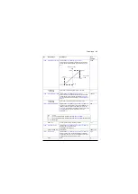
Defines the activation delay for relay output RO2.
0.0 s
t
On
=
t
Off
=
0.0…3000.0 s
Activation delay for RO2.
10 = 1 s
)
Defines the deactivation delay for relay output RO2. See
parameter
.
0.0 s
0.0…3000.0 s
Deactivation delay for RO2.
10 = 1 s
Displays the value of analog input AI2 in mA or V
(depending on whether the input is set to current or
voltage).
This parameter is read-only.
-
-22.000…22.000 mA
or V
Value of analog input AI2.
1000 = 1 mA
or V
Displays the value of analog input AI2 after scaling. See
parameter
.
This parameter is read-only.
-
-32768.000
…32767.000
Scaled value of analog input AI2.
1 = 1
Forced value that can be used instead of the true reading
of the input. See parameter
0.000 mA
-22.000…22.000 mA
or V
Forced value of analog input AI2.
1000 = 1 mA
or V
Shows the position of the hardware current/voltage
selector on the I/O extension module.
Note: The setting of the current/voltage selector must
match the unit selection made in parameter
. I/O module reboot either by cycling the power or
is required to
validate any changes in the hardware settings.
-
V
Volts.
2
No.
Name/Value
Description
Def/
FbEq16
1
0
1
0
t
On
t
Off
t
On
t
Off
Status of selected
source
RO status
Time
Summary of Contents for ACS880 ESP
Page 1: ...ABB industrial drives Firmware manual ACS880 PCP ESP control program ...
Page 4: ......
Page 28: ...28 PCP ESP control start up ...
Page 30: ...30 Using the control panel ...
Page 94: ...94 Standard programposi features ...
Page 100: ...100 Default control connections ...
Page 360: ...360 Parameters ...
Page 436: ...436 Fault tracing ...
Page 486: ...486 Control chain diagrams ...
Page 492: ...492 Appendix ESP with step up transformer and sine filter ...
Page 494: ...Contact us www abb com drives www abb com drivespartners 3AXD50000016186 Rev B EN 2015 10 27 ...


