84 Standard programposi features
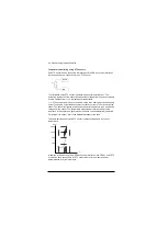
Temperature monitoring using PTC sensors
One PTC sensor can be connected to digital input DI6. FEN-xx encoder interfaces
(optional) also have a connection for one PTC sensor.
The resistance of the PTC sensor increases when its temperature rises. The
increasing resistance of the sensor decreases the voltage at the input, and eventually
its state switches from 1 to 0, indicating overtemperature.
1…3 PTC sensors can also be connected in series to an analog input and an analog
output. The analog output feeds a constant excitation current of 1.6 mA through the
sensor. The sensor resistance increases as the motor temperature rises, as does the
voltage over the sensor. The temperature measurement function calculates the
resistance of the sensor and generates an indication if overtemperature is detected.
For wiring of the sensor, refer to the Hardware Manual of the drive.
The figure below shows typical PTC sensor resistance values as a function of
temperature.
In addition to the above, optional FEN-xx encoder interfaces, and FEX-01 and FPTC-
01 modules have connections for PTC sensors. Refer to the module-specific
documentation for more information.
DI6
+24VD
T
100
550
1330
4000
Ohm
T
Summary of Contents for ACS880 ESP
Page 1: ...ABB industrial drives Firmware manual ACS880 PCP ESP control program ...
Page 4: ......
Page 28: ...28 PCP ESP control start up ...
Page 30: ...30 Using the control panel ...
Page 94: ...94 Standard programposi features ...
Page 100: ...100 Default control connections ...
Page 360: ...360 Parameters ...
Page 436: ...436 Fault tracing ...
Page 486: ...486 Control chain diagrams ...
Page 492: ...492 Appendix ESP with step up transformer and sine filter ...
Page 494: ...Contact us www abb com drives www abb com drivespartners 3AXD50000016186 Rev B EN 2015 10 27 ...

