Nominal input current (rms) at 40 °C (104 °F)
I
1
Apparent power (no overload)
S
n
Maximum output current. Available for 10 seconds at start, otherwise as long as allowed by drive
temperature. 140% … 200% of
I
Hd
, depending on power rating.
I
max
Continuous rms output current. No overload capability at 40 °C (104 °F). This is indicated in the
type designation label as output current
I
2
.
I
2
Typical motor power in no-overload use
P
n
Continuous rms output current allowing 10% overload for 1 minute every 5 minutes
I
Ld
Typical motor power for light-duty use
P
Ld
Continuous rms output current allowing 50% overload for 1 minute every 5 minutes
I
Hd
Typical motor power for heavy-duty use
P
Hd
Note:
To achieve the rated motor power given in the table, the rated current of the drive must be higher than
or equal to the rated motor current. The power ratings apply to most IEC 34 motors at the nominal voltage of
the drive.
ABB recommends to select the drive, motor and gear combination for the required motion profile with the
DriveSize dimensioning tool available from ABB.
■
When is derating necessary
Derate the continuous output current of the drive if
• ambient temperature e40 °C (+104 °F) or
• drive is installed higher than 1000 m (3280 ft) above sea level
• switching frequency is other than default
• the minimum requirements of motor cable length are not met (see chapter d
u
/d
t
filters
and sine filters)
• DC voltage boost feature is used.
Note:
The final derating factor is a multiplication of all applicable derating factors.
■
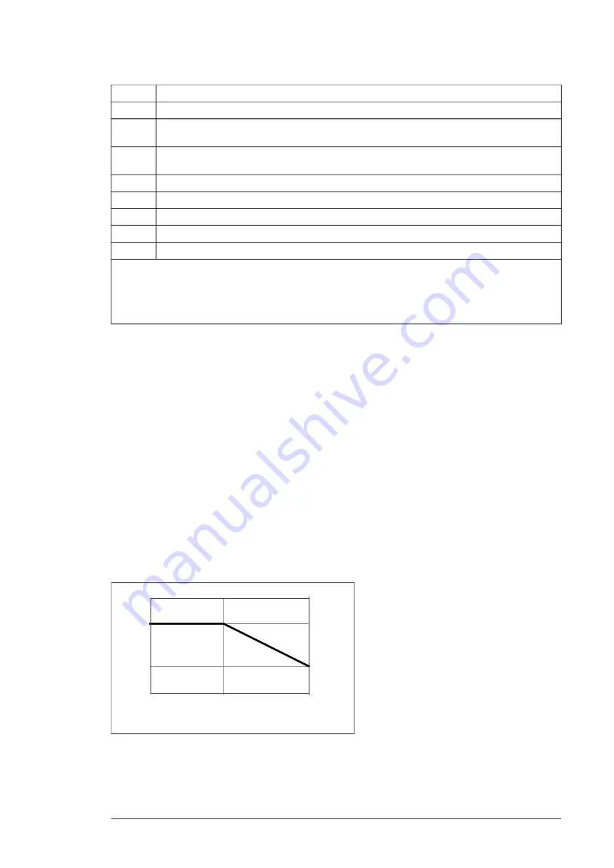
Surrounding air temperature derating
In the temperature range +40…55 °C (+104…131 °F), the rated output current is derated
by 1% for every added 1 °C (1.8 °F) as follows. Calculate the output current by multiplying
the current given in the rating table by the derating factor.
1.00
0.85
+40 °C
+55 °C
+104 °F
+131 °F
k
T
Technical data 181
Summary of Contents for ACS880-14
Page 1: ...ABB INDUSTRIAL DRIVES ACS880 14 drive modules 132 400 kW 200 400 hp Hardware manual...
Page 2: ......
Page 4: ......
Page 14: ...14...
Page 24: ...24...
Page 30: ...30...
Page 54: ...54...
Page 64: ...64...
Page 98: ...98...
Page 114: ...With twin connectors in the control panel holder 1 2 3 1 114 Electrical installation...
Page 115: ...With FDPI 02 modules OPEN TERMIN ATED 1 1 2 2 OPEN TERMINATED 3 Electrical installation 115 11...
Page 142: ...4 5 6 3 3 1 1 1 1 2 142 Installation example with full cabling panels option H381...
Page 150: ...150 Installation example with full cabling panels option H381...
Page 156: ...156...
Page 204: ...Standard configuration 204 Dimension drawings...
Page 206: ...Drive module with options 0B051 H356 0H371 206 Dimension drawings...
Page 207: ...Configuration with option H381 3AXD50000323210 Dimension drawings 207...
Page 208: ...LCL filter module 208 Dimension drawings...
Page 212: ...External control unit 3AXD50000011687 212 Dimension drawings...
Page 230: ...Declaration of conformity 230 The Safe torque off function...
Page 241: ...241...
Page 246: ...246...


