


Appendix A Hardware Units
CI856 and TP856 – S100 I/O Interface
3BSE 027 941 R301
173
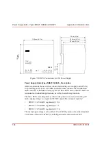
CI856 and TP856 – S100 I/O Interface
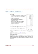
Key Features
•
Provides one S100 I/O port, (a 36 pin centerline
miniature ribbon connector located on the TP856
Baseplate).
•
Simple DIN-rail mounting
•
The CI856 handles I/O scanning and updating of
S100 I/O units located in up to five I/O racks. The
minimum cyclic scan/update interval is 0.2ms,
though this will depend on I/O type and number of
I/O points.
•
Pre-set, two-letter Alpha code locking device
installed in unit base prevents mounting of
incompatible components.
Description
The CI856/TP856 connects S100 I/O to AC 800M.The
TP856 Baseplate has one 36-pin centerline miniature
ribbon connector for connecting S100 I/O racks. The
baseplate has a code lock, see
prevents installation of an incorrect type of unit onto the
TP856 Baseplate.
The CI856 expansion unit contains the CEX-bus logic,
S100 I/O-bus logics, CPU and a DC/DC converter that
supplies appropriate voltages from the +24V supply, via
the CEX-bus.
F
R
TO
CI856
I/O
Summary of Contents for AC 800M
Page 1: ...ControlIT AC 800M Version 2 1 Controller Hardware Hardware and Operation...
Page 2: ......
Page 3: ...Controller Hardware Hardware and Operation ControlIT AC 800M Version 2 1...
Page 10: ...7DEOH RI RQWHQWV 10 3BSE 027 941 R301...
Page 20: ...Related Documentation About This Book 20 3BSE 027 941 R301...
Page 26: ...Operating Environment Safety Summary 26 3BSE 027 941 R301...
Page 42: ...Product Release History Section 1 Introduction 42 3BSE 027 941 R301...
Page 108: ...Powering from an External 24 V DC Source Section 3 Configuration 108 3BSE 027 941 R301...
Page 118: ...Verification of Redundant CPU Section 4 Operation 118 3BSE 027 941 R301...
Page 212: ...Low Voltage Directive LVD Appendix D Directive Considerations 212 3BSE 027 941 R301...
Page 214: ...Hazardous Location Approval Appendix E Standards 214 3BSE 027 941 R301...
Page 228: ...QGH 228 3BSE 027 941 R301...
Page 229: ......