


Section 2 Installation
Installing the S100 I/O Interface, CI856/TP856
3BSE 027 941 R301
75
Installing the S100 I/O Interface, CI856/TP856
The CI856 is powered from the processor unit via the CEX-bus and requires
therefore no additional external power source.
Use the following procedure to install the CI856/TP856:
1.
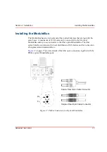
Mount the unit on the DIN-rail, see
Mounting AC 800M Units onto DIN-Rail
Installing the PM8xx/TP830 Processor Unit in Single
2.
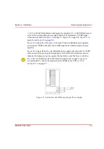
Connect the S100 I/O cable, TK575/TK580, to the contact on the baseplate. A
bus extender, DSBC174/DSBC176/DSBC173A, must be used.
S100 I/O Connection and Installation
Connect the S100 I/O rack cable TK575/TK580 to the “I/O-labeled” 36-pin
centerline miniature ribbon connector located on TP856.
Installation of S100 I/O
For installation of the S100 I/O-related components, see
Summary of Contents for AC 800M
Page 1: ...ControlIT AC 800M Version 2 1 Controller Hardware Hardware and Operation...
Page 2: ......
Page 3: ...Controller Hardware Hardware and Operation ControlIT AC 800M Version 2 1...
Page 10: ...7DEOH RI RQWHQWV 10 3BSE 027 941 R301...
Page 20: ...Related Documentation About This Book 20 3BSE 027 941 R301...
Page 26: ...Operating Environment Safety Summary 26 3BSE 027 941 R301...
Page 42: ...Product Release History Section 1 Introduction 42 3BSE 027 941 R301...
Page 108: ...Powering from an External 24 V DC Source Section 3 Configuration 108 3BSE 027 941 R301...
Page 118: ...Verification of Redundant CPU Section 4 Operation 118 3BSE 027 941 R301...
Page 212: ...Low Voltage Directive LVD Appendix D Directive Considerations 212 3BSE 027 941 R301...
Page 214: ...Hazardous Location Approval Appendix E Standards 214 3BSE 027 941 R301...
Page 228: ...QGH 228 3BSE 027 941 R301...
Page 229: ......


