


Section 2 Installation
Power Supply Supervision
3BSE 027 941 R301
83
+ 24 V on the SA/SB indicates working power supplies. 0 V on SA/SB indicates an
error in the corresponding power supply and lack of redundancy. SA/SB signal
connection is shown in
page 83 and
on page 82 show redundant power supplies
powering AC 800M units. Here the SA/SB signals also indicate physical power
supplies.
on page 84 shows one redundant power supply powering the AC 800M
units and one for powering field equipment. An SA/SB error indication can not
indicate which physical power supply that has failed, only that there is a failure.
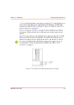
To avoid error indications from SA/SB when single power supply is used, it is
recommended to connect the input terminals SA/SB on the CPU to +24 V,
see
Figure 21. Connection of SA/SB using Single Power Supply
PM861
L+
L–
SA
SB
+24 V
0 V
Summary of Contents for AC 800M
Page 1: ...ControlIT AC 800M Version 2 1 Controller Hardware Hardware and Operation...
Page 2: ......
Page 3: ...Controller Hardware Hardware and Operation ControlIT AC 800M Version 2 1...
Page 10: ...7DEOH RI RQWHQWV 10 3BSE 027 941 R301...
Page 20: ...Related Documentation About This Book 20 3BSE 027 941 R301...
Page 26: ...Operating Environment Safety Summary 26 3BSE 027 941 R301...
Page 42: ...Product Release History Section 1 Introduction 42 3BSE 027 941 R301...
Page 108: ...Powering from an External 24 V DC Source Section 3 Configuration 108 3BSE 027 941 R301...
Page 118: ...Verification of Redundant CPU Section 4 Operation 118 3BSE 027 941 R301...
Page 212: ...Low Voltage Directive LVD Appendix D Directive Considerations 212 3BSE 027 941 R301...
Page 214: ...Hazardous Location Approval Appendix E Standards 214 3BSE 027 941 R301...
Page 228: ...QGH 228 3BSE 027 941 R301...
Page 229: ......


