


Section 3 Configuration
General Information
3BSE 027 941 R301
91
Section 3 Configuration
General Information
Using the engineering tool Control Builder, it is possible to configure hardware (I/O
and communication units) and make application programs with control languages
according to IEC 61131-3. Programs can be compiled and run off-line as an aid to
process simulation before finally downloading an application to the controller. The
Control Builder offers a set of options, each with its own set of properties. Simply
select the option that is closest to system requirements. For further information,
see
•
Control Builder M Documentation – for configuration information
•
Control Software Documentation – for available functionality.
The Control Builder Online Help facility provides detailed step-by-step information
when creating an application for the AC 800M Controller.
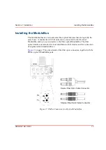
Connecting Control Builder M
The Control Builder installed in a PC is normally connected to the AC 800M
Controller via the Control Network and the CN1 or CN2 ports on the controller
(see
Alternatively the Control Builder may be connected via the COM4 port (RS232-C)
on the AC 800M Controller. Use the tool cable TK212 and a serial port on the PC.
In redundant configuration the Control Builder is connected to the Primary CPU
COM4 port. The CB can not be accessed by the Backup CPU.
Note that if the firmware in the AC 800M is not running correctly, then it is likely
that the CN1 and CN2 ports will not be usable. However, the connection via the
COM4 port is always available.
Summary of Contents for AC 800M
Page 1: ...ControlIT AC 800M Version 2 1 Controller Hardware Hardware and Operation...
Page 2: ......
Page 3: ...Controller Hardware Hardware and Operation ControlIT AC 800M Version 2 1...
Page 10: ...7DEOH RI RQWHQWV 10 3BSE 027 941 R301...
Page 20: ...Related Documentation About This Book 20 3BSE 027 941 R301...
Page 26: ...Operating Environment Safety Summary 26 3BSE 027 941 R301...
Page 42: ...Product Release History Section 1 Introduction 42 3BSE 027 941 R301...
Page 108: ...Powering from an External 24 V DC Source Section 3 Configuration 108 3BSE 027 941 R301...
Page 118: ...Verification of Redundant CPU Section 4 Operation 118 3BSE 027 941 R301...
Page 212: ...Low Voltage Directive LVD Appendix D Directive Considerations 212 3BSE 027 941 R301...
Page 214: ...Hazardous Location Approval Appendix E Standards 214 3BSE 027 941 R301...
Page 228: ...QGH 228 3BSE 027 941 R301...
Page 229: ......


