


Installing the SD82x Power Supply
Section 2 Installation
78
3BSE 027 941 R301
Installing the SD82x Power Supply
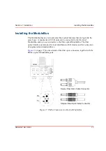
Use the following procedure to install the SD821, SD822 and SD823 power supply
units.
1.
Mount the selected unit onto the DIN-rail at the required position.
2.
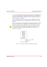
Set the mains switch on the front of the power supply unit to the required
voltage:
a.
115 V for 110–120 V AC
b.
230 V for 220 –240 V AC (default position on delivery).
3.
Connect the mains supply to the L(ive) and N(eutral) terminals.
4.
Connect the protective ground to the PE terminal.
5.
Connect the output cable to terminals L+ (+24 V) and L– (0 V).
The power supply unit’s L– output (0 V) can be used without being grounded.
If grounding is required, the power supply unit’s L– output (0 V) can be
grounded directly or via a suitable resistor.
All terminals marked L+ are internally connected within the power supply unit.
The same applies for terminals marked L–.
Summary of Contents for AC 800M
Page 1: ...ControlIT AC 800M Version 2 1 Controller Hardware Hardware and Operation...
Page 2: ......
Page 3: ...Controller Hardware Hardware and Operation ControlIT AC 800M Version 2 1...
Page 10: ...7DEOH RI RQWHQWV 10 3BSE 027 941 R301...
Page 20: ...Related Documentation About This Book 20 3BSE 027 941 R301...
Page 26: ...Operating Environment Safety Summary 26 3BSE 027 941 R301...
Page 42: ...Product Release History Section 1 Introduction 42 3BSE 027 941 R301...
Page 108: ...Powering from an External 24 V DC Source Section 3 Configuration 108 3BSE 027 941 R301...
Page 118: ...Verification of Redundant CPU Section 4 Operation 118 3BSE 027 941 R301...
Page 212: ...Low Voltage Directive LVD Appendix D Directive Considerations 212 3BSE 027 941 R301...
Page 214: ...Hazardous Location Approval Appendix E Standards 214 3BSE 027 941 R301...
Page 228: ...QGH 228 3BSE 027 941 R301...
Page 229: ......


