


Section 5 Maintenance
Corrective Maintenance Procedures
3BSE 027 941 R301
127
6.
Reconnect the Power Supply Socket to the new processor unit.
7.
Reconnect the optical ModuleBus and RCU Link Cable.
8.
Press the INIT push button on the replaced processor unit. Observe the
startup procedure and make sure that Dual mode is reached, that the
Dual LED is lit on both processor units.
Corrective Maintenance Procedures
Changing Fuses – ModuleBus and CEX-bus
To change the TP830 internal ModuleBus and CEX-bus fuses:
1.
Using a blade screwdriver, release the two spring-loaded captive screws on the
PM8xx cover.
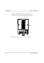
2.
Carefully remove the processor unit
3.
Identify both the ModuleBus and CEX-bus fuse-holders to the right on the
TP830 Baseplate.
–
Upper Fuse-holder – ModuleBus – fuse 2AF
–
Lower Fuse-holder – CEX-bus – fuse 3.15AF
4.
Using a blade screwdriver, carefully unscrew the fuse-holder containing the
defective fuse.
5.
Remove the fuse.
6.
Insert a new fuse and replace the fuse holder.
–
Upper Fuse-holder – ModuleBus – fuse 2AF
–
Lower Fuse-holder – CEX-bus – fuse 3.15AF
7.
Replace the processor unit and tighten the cover screws.
The just replaced (broken) CPU might still have the IP address of the primary
CPU. If it, for example, is installed later on for testing on the same control
network it might disturb the communication to the active system running the
application. Therefore used the IP Config tool to modify the IP address of the
just replaced CPU immediately.
Summary of Contents for AC 800M
Page 1: ...ControlIT AC 800M Version 2 1 Controller Hardware Hardware and Operation...
Page 2: ......
Page 3: ...Controller Hardware Hardware and Operation ControlIT AC 800M Version 2 1...
Page 10: ...7DEOH RI RQWHQWV 10 3BSE 027 941 R301...
Page 20: ...Related Documentation About This Book 20 3BSE 027 941 R301...
Page 26: ...Operating Environment Safety Summary 26 3BSE 027 941 R301...
Page 42: ...Product Release History Section 1 Introduction 42 3BSE 027 941 R301...
Page 108: ...Powering from an External 24 V DC Source Section 3 Configuration 108 3BSE 027 941 R301...
Page 118: ...Verification of Redundant CPU Section 4 Operation 118 3BSE 027 941 R301...
Page 212: ...Low Voltage Directive LVD Appendix D Directive Considerations 212 3BSE 027 941 R301...
Page 214: ...Hazardous Location Approval Appendix E Standards 214 3BSE 027 941 R301...
Page 228: ...QGH 228 3BSE 027 941 R301...
Page 229: ......


