16-4
C
HAPTER
16: D
EDICATED
/L
EASED
L
INE
AND
SYNCHRONOUS
APPLICATIONS
3
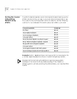
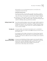
Set DIP switch 10 OFF. This tells the Courier V.Everything modem to load
NVRAM settings at power-on It does not matter whether the Courier
V.Everything modem is in Dumb or Smart mode (DIP switch 8).
4
Decide which modem is to be the calling modem and which the
answering modem.
5
Set the answering modem to Auto Answer, DIP switch 5 OFF, and the
calling modem to Auto Answer suppressed, DIP switch 5 ON.
6
Power off and power on the modems. This initiates the new DIP switch
settings and loads the power-on defaults, including &L1. The modems go
off hook and establish the connection.
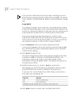
If the modems cannot restore the connection and you did not set the
Courier V.Everything modem to &S2, the reason could be a keypress
abort. If the problem persists, however, you may need to call your
telephone company to have them check your line.
Dial Using V.25
bis
Software
To make synchronous connections using V.25
bis
communications
software, you must first configure your modem using AT commands.
Once the modem is configured, run your communications software.
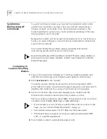
Configuring th
Courier V.Everything
Modem
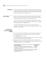
Before you attempt to connect to a synchronous network, you must first
configure your modem using an asynchronous device, such as a terminal
or a computer running standard asynchronous communications software.
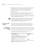
1
Find out the protocol being used for dialing and answering in your
software and then set your modem to dial using it.
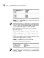
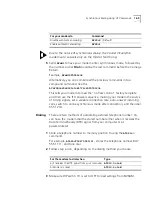
Example:
Sending
AT&M7&W
would select HDLC.
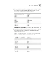
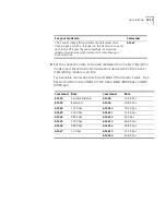
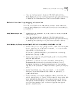
For your modem to
Command
Dial using the BISYNC protocol.
Your modem and the remote device must use the same
8-bit data format. The character length must be 7 bits and
either ODD or EVEN parity (ODD is preferred), or 8 bits
and NO parity.
AT&M6
Dial using the High Level Data Link Control (HDLC)
protocol.
AT&M7
Summary of Contents for Courier
Page 12: ......
Page 28: ...1 14 CHAPTER 1 CONNECTING TO YOUR ISP ...
Page 36: ...3 4 CHAPTER 3 UPGRADING YOUR MODEM ...
Page 58: ...6 6 CHAPTER 6 WORKING WITH MEMORY ...
Page 64: ...8 4 CHAPTER 8 CONTROLLING EIA 232 SIGNALING ...
Page 72: ...9 8 CHAPTER 9 ACCESSING AND CONFIGURING THE COURIER V EVERYTHING MODEM REMOTELY ...
Page 80: ...10 8 CHAPTER 10 CONTROLLING DATA RATES ...
Page 96: ...12 6 CHAPTER 12 FLOW CONTROL ...
Page 108: ...13 12 CHAPTER 13 HANDSHAKING ERROR CONTROL DATA COMPRESSION AND THROUGHPUT ...
Page 112: ...14 4 CHAPTER 14 DISPLAYING QUERYING AND HELP SCREENS ...
Page 122: ...15 10 CHAPTER 15 TESTING THE CONNECTION ...
Page 142: ...17 8 CHAPTER 17 TROUBLESHOOTING ...
Page 156: ...A 14 APPENDIX A S REGISTERS ...
Page 172: ...B 16 APPENDIX B ALPHABETIC COMMAND SUMMARY ...
Page 178: ...C 6 APPENDIX C FLOW CONTROL TEMPLATE ...
Page 186: ...E 4 APPENDIX E V 25 BIS REFERENCE ...


