8-2
C
HAPTER
8: C
ONTROLLING
EIA-232
SIGNALING
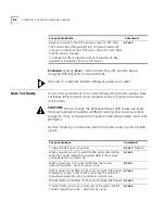
Example:
Sending
AT&D1
before connecting with another device,
dropping DTR will enter Command Mode.
DIP switch 1 overrides the &Dn setting at power on or reset.
Data Set Ready
Under normal conditions, the Courier V.Everything modem sends a Data
Set Ready (DSR) signal to your computer when it is ready to send and
receive data.
CAUTION:
Do not change the default setting of &S0 unless you know
that your installation requires a different setting. Few communications
programs, if any, will require the Courier V.Everything modem to control
DSR (&S1).
Use the following command to control how the modem sends the DSR
signal.
Respond normally to the DTR signal and reset on DTR drop.
The Courier V.Everything modem will not accept commands
until your computer sends a DTR signal. The call will end when
the DTR signal is dropped.
To change the DTR recognition time, set S-Register 25. See
Appendix A,
S-Registers
for more information.
AT&D3
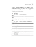
For your modem to
Command
For your modem
Command
To send the DSR signal at all times.
AT&S0
(Default)
When originating a call, to send the DSR signal after dialing
when the Courier V.Everything modem detects the remote
analogue device’s answer tone
AT&S1
When answering a call, to send DSR after the Courier
V.Everything mode
sends its answer tone.
AT&S1
After sending Carrier Detect (CD), to send a pulsed DSR signal,
followed by a Clear to Send (CTS) signal. Use this option for
specialised equipment such as automatic callback units.
AT&S2
After sending Carrier Detect (CD), to send a pulsed DSR signal.
AT&S3
To send a DSR signal to your computer at the same time the
Courier V.Everything mode
sends the CD signal.
AT&S4
Summary of Contents for Courier
Page 12: ......
Page 28: ...1 14 CHAPTER 1 CONNECTING TO YOUR ISP ...
Page 36: ...3 4 CHAPTER 3 UPGRADING YOUR MODEM ...
Page 58: ...6 6 CHAPTER 6 WORKING WITH MEMORY ...
Page 64: ...8 4 CHAPTER 8 CONTROLLING EIA 232 SIGNALING ...
Page 72: ...9 8 CHAPTER 9 ACCESSING AND CONFIGURING THE COURIER V EVERYTHING MODEM REMOTELY ...
Page 80: ...10 8 CHAPTER 10 CONTROLLING DATA RATES ...
Page 96: ...12 6 CHAPTER 12 FLOW CONTROL ...
Page 108: ...13 12 CHAPTER 13 HANDSHAKING ERROR CONTROL DATA COMPRESSION AND THROUGHPUT ...
Page 112: ...14 4 CHAPTER 14 DISPLAYING QUERYING AND HELP SCREENS ...
Page 122: ...15 10 CHAPTER 15 TESTING THE CONNECTION ...
Page 142: ...17 8 CHAPTER 17 TROUBLESHOOTING ...
Page 156: ...A 14 APPENDIX A S REGISTERS ...
Page 172: ...B 16 APPENDIX B ALPHABETIC COMMAND SUMMARY ...
Page 178: ...C 6 APPENDIX C FLOW CONTROL TEMPLATE ...
Page 186: ...E 4 APPENDIX E V 25 BIS REFERENCE ...


