C-2
A
PPENDIX
C: F
LOW
C
ONTROL
T
EMPLATE
* Detected by each modem from the AT prefix of the &W command that
writes your defaults to NVRAM. Set your software to the desired word
length, parity, and serial port rate defaults before sending the modem the
AT... &W string.
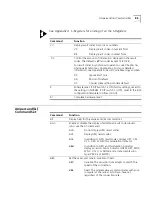
Error control/sync
&M4
Normal/error control
Link rate select
&N0
Variable
Pulse dialing type
&P0
U.S./Canada
Record data hardware
flow control
&R2
Enabled
Data Set Ready
&S0
Always on
Remote Digital
Loopback (RDL)
&T5
Deny RDL
Externals Only:
Synchronous transmit
clock source
&X0
Courier
Break handling
&Y1
Clear buffer, send immediately
Stored telephone
number
&Z0-9=0
Blank
EXTERNALS ONLY:
Synch Clock Speed
%N6
9600 bps
Caller ID
#CID=0
Caller ID disabled
Word length*
8
Parity*
0
None
DTE rate* (Kbps)
19.2
_
NVRAM Options
Setting
Description
Summary of Contents for Courier
Page 12: ......
Page 28: ...1 14 CHAPTER 1 CONNECTING TO YOUR ISP ...
Page 36: ...3 4 CHAPTER 3 UPGRADING YOUR MODEM ...
Page 58: ...6 6 CHAPTER 6 WORKING WITH MEMORY ...
Page 64: ...8 4 CHAPTER 8 CONTROLLING EIA 232 SIGNALING ...
Page 72: ...9 8 CHAPTER 9 ACCESSING AND CONFIGURING THE COURIER V EVERYTHING MODEM REMOTELY ...
Page 80: ...10 8 CHAPTER 10 CONTROLLING DATA RATES ...
Page 96: ...12 6 CHAPTER 12 FLOW CONTROL ...
Page 108: ...13 12 CHAPTER 13 HANDSHAKING ERROR CONTROL DATA COMPRESSION AND THROUGHPUT ...
Page 112: ...14 4 CHAPTER 14 DISPLAYING QUERYING AND HELP SCREENS ...
Page 122: ...15 10 CHAPTER 15 TESTING THE CONNECTION ...
Page 142: ...17 8 CHAPTER 17 TROUBLESHOOTING ...
Page 156: ...A 14 APPENDIX A S REGISTERS ...
Page 172: ...B 16 APPENDIX B ALPHABETIC COMMAND SUMMARY ...
Page 178: ...C 6 APPENDIX C FLOW CONTROL TEMPLATE ...
Page 186: ...E 4 APPENDIX E V 25 BIS REFERENCE ...


