


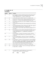


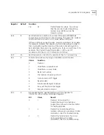

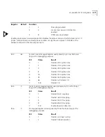


A
S-R
EGISTERS
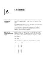
Understanding
Bit-Mapped
S-Registers
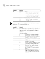
A bit-mapped S-Register uses one number to describe a collection of
settings. Bit-mapping allows us to pack a lot of information in a small
space.
Bit-mapped registers are in the form of Sr.b=n, where r is the bit-mapped
register;.b is the bit; n is 0 (off) or 1 (on).
The modem displays the value of an S-Register, as a decimal value
between 0 and 255. The modem, however, understands the decimal
value as a collection of binary digits (bits).
How bits are
mapped to decimal
values
Bits can be mapped into decimal values. Each bit can be either on (1) or
off (0). Eight bits create 256 unique combinations of 1s and 0s. Each of
the eight bits can be assigned a number corresponding to its position:
b b b b b b b b
7 6 5 4 3 2 1 0
Also, each bit can be assigned a value corresponding to its number:
Bit
Value
7
2
7
=
128
6
2
6
=
64
5
2
5
=
32
4
2
4
=
16
3
2
3
=
8
2
2
2
=
4
1
2
1
=
2
0
2
0
=
1
Summary of Contents for Courier
Page 12: ......
Page 28: ...1 14 CHAPTER 1 CONNECTING TO YOUR ISP ...
Page 36: ...3 4 CHAPTER 3 UPGRADING YOUR MODEM ...
Page 58: ...6 6 CHAPTER 6 WORKING WITH MEMORY ...
Page 64: ...8 4 CHAPTER 8 CONTROLLING EIA 232 SIGNALING ...
Page 72: ...9 8 CHAPTER 9 ACCESSING AND CONFIGURING THE COURIER V EVERYTHING MODEM REMOTELY ...
Page 80: ...10 8 CHAPTER 10 CONTROLLING DATA RATES ...
Page 96: ...12 6 CHAPTER 12 FLOW CONTROL ...
Page 108: ...13 12 CHAPTER 13 HANDSHAKING ERROR CONTROL DATA COMPRESSION AND THROUGHPUT ...
Page 112: ...14 4 CHAPTER 14 DISPLAYING QUERYING AND HELP SCREENS ...
Page 122: ...15 10 CHAPTER 15 TESTING THE CONNECTION ...
Page 142: ...17 8 CHAPTER 17 TROUBLESHOOTING ...
Page 156: ...A 14 APPENDIX A S REGISTERS ...
Page 172: ...B 16 APPENDIX B ALPHABETIC COMMAND SUMMARY ...
Page 178: ...C 6 APPENDIX C FLOW CONTROL TEMPLATE ...
Page 186: ...E 4 APPENDIX E V 25 BIS REFERENCE ...