background image

Page 3-1

PRELIMINARY INFORMATION

ROM  Version  Tests

Requirements

P erform  th e  f o l l o w i n g  s t eps  to  d e t er m in e  th e  R O M

Y ou  w i l l  n e e d  t h e  f o l l o w i n g  t o o l s  an d  t e s t  e q u i p -

ment to install  the  Wi n c hester System:

version:

"I'urn on  the Computer.

• 

At  th e p r o m p t ,  p r e ss  the V  key.  If  the  auto-boot
f unction  i s  enabled,  tur n  th e  c o m p u ter  on  a n d
p ress the DELETE  key,  then  V  k ey.  You  sh o u l d
n ow  see a  message on  the  m o n i t o r  r esembl i n g
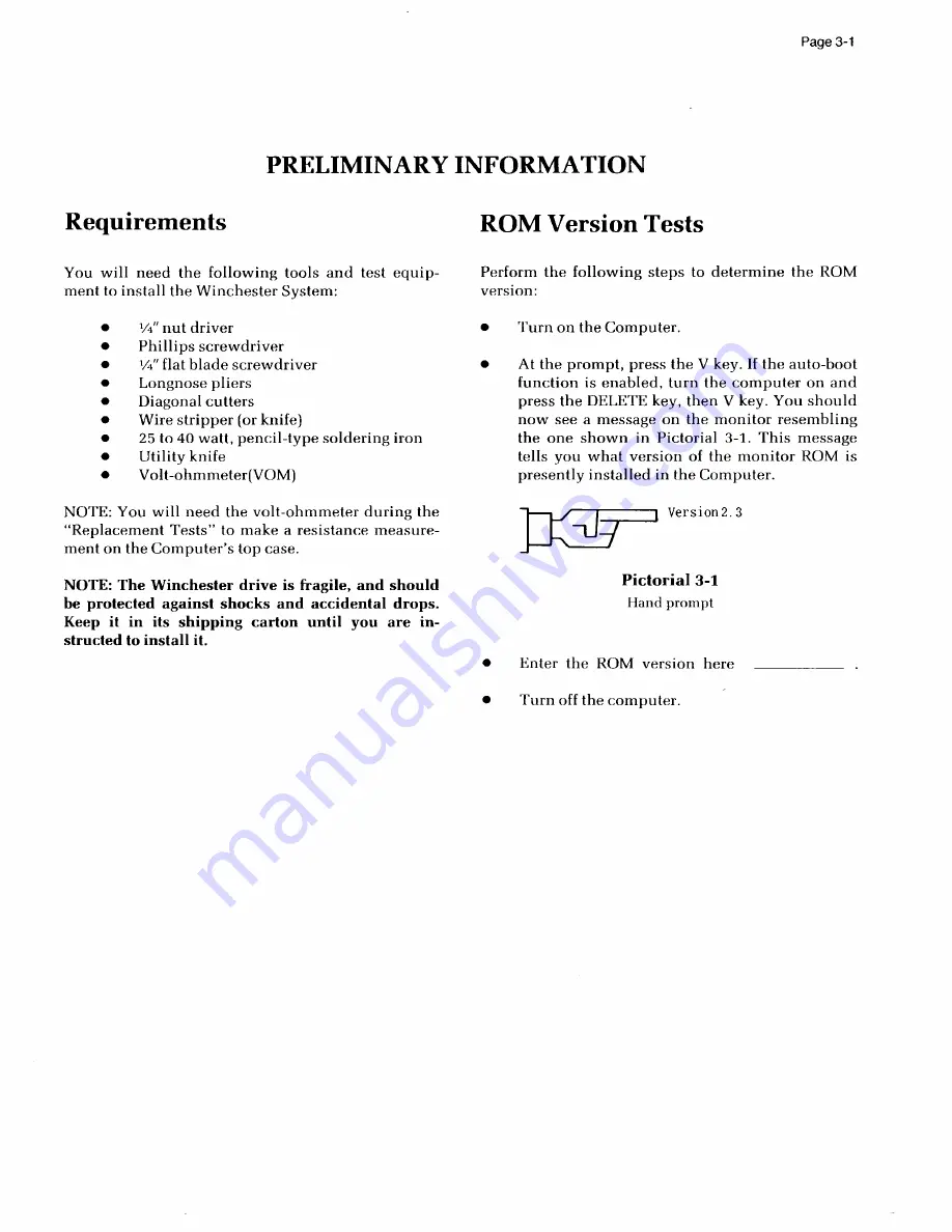
the  one  sh ow n  i n  P i c t o r ia l  3 - 1 .  T h i s m e ssage
t ells  you  w h a t  v e r s ion  o f  t h e  m o n i t o r  RO M  i s

presently  installed  in  the  Compu t er .

V~" nut driver

Phillip

screwdriver

' t~" flat blade screwdr i v er

Longnose pliers
Diagonal  cutters
Wire stripper  (or  kni fe)
25 to 40 watt,  pencil-type  soldering  iron

U tility  k n i f e

V olt-ohmm eter(VOM )

Version 2. 3

N OTE:  You  w i l l  n eed  th e  v o l t - o h m m e ter  d u r in g  th e

"Replacement  Tests"  to  m ake  a  resistance  measure-

ment on  the Computer's  top  case.

NOTE: The  Winchester  drive  is  fragile,  and  should

be protected against shocks and accidental drops.

K eep it  i n  i t s  s h i p p ing  c a rton  u n ti l  y o u  a r e  i n -
structed to install it.

Pictorial 3-1

Hand prompt

• 

E nt er  th e  R O M  v e r s i o n  h e r e

• 

T u r n o f f t h e  comp u t e r.

Содержание Z-100 Series

Страница 1: ...data systems g I TN THE QUALITY GOES IN BEFORE THE MANE GOES ON DESKTOP COMPUTER SYSTENS Z 100 USER S MANUAL WINCHESTER SUPPLEMENT...

Страница 2: ...Z 10 eri es User s Manual Winchester u lcm ent I aa systems...

Страница 3: ...atures of PART PART Operation Modifying the Default Boot Partition Partition Maintenance Finishing PART Establishing the Default Boot Partition Z DOS Booting from the Winchester CP M 85 Booting from t...

Страница 4: ...hat will allow you to store the equivalent of several dozen floppy diskettes inside your Computer ready for immediate access in your daily business needs Besides additional on line capacity of stored...

Страница 5: ...ches ter drive may fail to operate If this occurs you should con tact your local ZDS representative for service The built in disk of your Winchester drive cannot be phys ically removed from the drive...

Страница 6: ...ppy disk drive actually rides on the surface of the disk The read write heads of both systems have the same function and are described on page 1 16 of your User s Manual The organization of the indivi...

Страница 7: ...B It may contain an operating system such as CP M 85 or Z DOS or may be used strictly for data storage The Winchester design in your Desktop Computer uses a single head per platter side and is totall...

Страница 8: ...the programs on either the Customer Demonstration Disk or the Utilities disk To use either diskette follow these general instructions Make sure your Computer is turned on and the hand prompt is showi...

Страница 9: ...g key The disk access indicator for the floppy disk drive will glow After a moment the first messages will appear on the screen If you are using the Customer Demonstration diskette turn to page 1 20 i...

Страница 10: ...d later for immediate use The VERIFY utility is supplied so that you may check the surface of your Winchester disk for bad sectors and lock out any that are found Where PREP destroys the data you have...

Страница 11: ...REP does test the surface of the disk for retention of data it will also destroy any data that you have recorded on the Winchester disk system If you do not want to destroy the data on your disk but s...

Страница 12: ...your Desktop Computer Then PREP will display messages that tell you what is happening as it prepares and tests your disk A chart of typical Win chester disk parameters is supplied in Appendix A along...

Страница 13: ...n orderto identify the type of Winchester drive you have installed Then PREPdisplays messages as it operates on the disk CAUTION Using PREPwill destroy all fi les on your Winchester disk Winchesterdis...

Страница 14: ...ill see the Z DOS system prompt If the disk has been previously prepared and PREP de tects no errors in the boot code or superblock explained later then the following five disk parameter questions wil...

Страница 15: ...e largest cylinder number will be entered Enter 200 the number in hexadecimal of the cylinder where the current applied to the write head is reduced to avoid overwriting track bounds and press the g g...

Страница 16: ...information for your hard disk the program will initialize the surface of the disk for the tests that follow The initialization process is similar to that used by the Z DOS and CP M 85 FORMAT utility...

Страница 17: ...P uses a diff erent code on each pass itmakes through the test If PREP finds questionable areas on the disk it stores the address where the error occurred and later places these addresses into a bad s...

Страница 18: ...event them from being used by the system for data storage It is normal to have a small number of bad sectors out of the five to twenty thousand located on the typical Winchester disk When the tests ar...

Страница 19: ...ition just as you would reformat a floppy disk However you will want to use the BACKUP utility before you do this See the discussion on BACKUP and RESTORE found later in this supplement When a bad sec...

Страница 20: ...at have failed since you last ran PREP Do you wish to proceed with VERIFY Y N Figure 3 The VERIFY initial display At the bottom of the display you will see Do you wish toproceed with VERIFY Y N If you...

Страница 21: ...the gg key The prompt will reappear allowing you to continue to enter additional bad sector addresses To end entering bad sector addresses press the Q key and then the g g g key The system will start...

Страница 22: ...tors the actual need for this utility as well as the other utilities on this disk will be minimal once your system has been in use for a month or two Failures due to contamination from smoke and dust...

Страница 23: ...ms on the same partition Each of the two standard partitions that exists on your Win chester disk when it is shipped from the factory occupies ap proximately one half of the total available Winchester...

Страница 24: ...stem to be used with each partition The percent of disk space allocated to each partition The name of the partition that is selected when you boot your computer system PART OPERATION In this part of t...

Страница 25: ...a partitionname and a system name and the amount of disk space allocated to each partition in percentages and in kilobytes PART also dynamically calculates and totals the size of all partitions as you...

Страница 26: ...iles on your Winchester disk NOTE You can use PART to select a different default boot partition without destroying software or data However you should not attempt to do this if you are unsure about th...

Страница 27: ...lobytes 1 Z DOS 2 CPM Z DOS CP ll 5000 5000 50 50 4 9 10 12 13 14 15 16 T otal Utilization Allocated unallocated 100 0 Defaultboot partition number 1 Z DOS Z DOS 10000 0 B Hodify default boot partitio...

Страница 28: ...pressing the g g or key The display is similar to the one that will appear the first time you run PART on a new Heath Zenith Data Systems Z 217 Winchester disk or immediately after you have run the P...

Страница 29: ...e selected by the boot process You will also see a prompt to Enter the number of the default boot partition at the bot tom of the screen Enter the number of the partition that you want to estab lish a...

Страница 30: ...lecting a Default Boot Partition If you try to enter a number for which there is no established partition on the table the Computer will simply not accept your entry and the cursor will remain at the...

Страница 31: ...is undefined will be displayed Now when you boot the system you will have to enter bootup commands that specify partition names and possibly also operating system names in order to boot up with any p...

Страница 32: ...ur screen will be similar to the one illustrated in Fig ure 9 PartitionName Operating System Name Percentage Kilobytes Z DOS CPM 50 50 5000 5000 1 Z DOS 2 CPM 3 4 5 6 7 8 9 10 11 12 13 14 15 16 Total...

Страница 33: ...this time you may choose to change the partition name delete the partition or leave it alone To change the partition s name type the new name If you use lower case letters they will be converted to u...

Страница 34: ...tely you will see the duplicate name error message after you make the default boot partition entry If you want to delete all the entries for this partition press SRBSKKKl will move up one row If you r...

Страница 35: ...he following are typical examples of operating system names CPM Z DOS USER DOS OTHER DOS At this time you may choose to change the operating system name or leave it alone To change the operating syste...

Страница 36: ...he l gg key If you wish to alter the operating system name type the new name and press the g gg key Once you press the g g g k ey the cursor will move to the percentage column The Percentage Column Th...

Страница 37: ...ave not allo cated all of the available disk space by the time you enter the percent figure for the 16th partition PART will automati cally allocate the remaining disk space to the 16th partition If y...

Страница 38: ...the cursor moves to the next row s parti tion name if you are currently working on one of the first 15 partitions or the default boot partition area if you are currently working on the 16th partition...

Страница 39: ...rmation and you do not want to establish any more partitions press the g g ke y The cursor will advance directly to the default boot partition area where you can establish the default boot partition o...

Страница 40: ...exit Choose desiredoption M or A If you press the jg key to make the changes you have selected to the Winchester disk you need to be aware that any data you have on the disk could be lost Make sure th...

Страница 41: ...l Z DOS and CP M ESTABLISHING THE OEFAULT BOOT PARTITION Use your Utilities disk and run PART as previously de scribed Press the g key to select option B of the menu to establish the default boot part...

Страница 42: ...key followed by the gg key In a moment the Z DOS initial messages will appear and you will be asked to enter the date If your disks have not been previously duplicated using the automatic MAKE utilit...

Страница 43: ...nd the number of free bytes for your files If any sectors were locked out that information will also be displayed Type the following COPY A E The E in the command represents the first Winchester drive...

Страница 44: ...is not set up to boot from the Winchester disk you will have to press the key t o stop any auto boot process and then press the g key and then the g key followed by the key The WinchesterLED disk ac c...

Страница 45: ...VERSION 2 2 101 01 28 83 A The A is the CP M system prompt You must now as sign your system to work with the CP M partition If you do not have 8 diskettes connected or turned on type the following AS...

Страница 46: ...o the Winchester disk Press the tlag key The CP M prompt will reappear You are now ready to format the partition Type FORMAT and press the g g g k ey The following will be dis played CP M 85 Format Ve...

Страница 47: ...MVCPM217 and press the Qgg ke y You will see the following MVCPM217 VERSION 2 2 101 CONSTRUCTING 64k CP M vers 2 2 READYFOR SYSGEN OR SAVE 38 CPM64 COM A You must now perform the SYSGEN operation bef...

Страница 48: ...ystem on your Winchester disk You will see FUNCTION COMPLETE DESTINATION DRIVE NAME OR RETURN TO REBOOTl Press the g II rJ key The CP M 85 prompt will appear on your screen Type the following for non...

Страница 49: ...Com puter If your Computer is not set up to boot from the Winchester disk you will have to press the I key to stop any auto boot process and then press the gkey and then the g key f ollowed by the ke...

Страница 50: ...tem by typing the partition name for instance Z DOS and pressing the tl gg k ey If you have selected a partition that has not been formatted the hand prompt will reappear on your screen The system may...

Страница 51: ...est partition numbers can be accessed by the system If you choose to boot from a Winchester partition then it and if available the next higher numbered Z DOS partition can be accessed by the system No...

Страница 52: ...Z DOS Instead when you boot CP M from the Winchester CP M partition of your choice that partition is automatically assigned drive name A The CP M command ASSIGN can then be used to assign drive name...

Страница 53: ...the partition s Use the Z DOS or CP M DIR command to list the names of the files Exclude any Z DOS files named COPYFILE DAT as they are batch files used by the Z DOS MAKE utility for installing the s...

Страница 54: ...me and extension to copy multiple files Complete the Process When you have finished copying all of the selected files to your Winchester partition s store the distribution disk s in a safe place Consu...

Страница 55: ...red extensionsuch as BACKFILE OOO BACKFILE 001 and so on The system backs up yourfi l es end to end to save floppy disk space The operation is further enhanced by providing an automatic FORMAT procedu...

Страница 56: ...the copy is valid and is identical to the original The system will prompt you to put the floppy disks into the disk drives as needed When the process is finished the Z DOS prompt will reappear To obt...

Страница 57: ...switches that may be used CP M 85 In this supplement you will learn just one of several methods of backup for your CP M 85 partition To backup the entire CP M 85 partition use the following instructio...

Страница 58: ...mand type BACKUP and press the jggg key Your display will show you the exact syntax and an explanation of the switches that may be used Restoration of the original files to the Winchester disk is also...

Страница 59: ...erations de scribed herein refer to your respective operating system man ual for complete details or contact Software Consultation by writing to Zenith Data Systems Corporation Software Consultation H...

Страница 60: ...use this utility whenever you move your Winchester disk system even from one table to another To operate the SHIP utility boot your Winchester Utilities disk and type SHIP and press the g g k ey You...

Страница 61: ...for the addresses of the shipping position for typical Winchester drives The system will correctly position the heads over unused disk space Remove any floppy disk in the system and turn off your Com...

Страница 62: ...nsult your dealer All amounts are listed in hexadecimal Manufacturer and Model No of Cylinders No of Write Precomp Step code Heads Curr en t Cylind er SHIP Cylinder Address Cylinder Seagate ST 506 ST...

Страница 63: ...e the external 8 inch floppy disk cable leading from the Z 207 Controller card to the back panel of your Computer Note any cables you remove and how they are positioned on their respec tive boards so...

Страница 64: ...r left corner of the board see inset 2 of the Figure Replace the board by gently pushing it straight down into the card cage Make sure that it slides down the guides provided and is completely pushed...

Страница 65: ...over of your Computer and make sure that it is completely latched into position Replace the power cord Your system is now ready to use with the PREP utility CAUTION Do not leave the jumper in place fo...

Страница 66: ...oot code 13 Bootup 6 8 19 22 23 24 25 27 30 33 41 43 44 48 49 Initialize 9 10 11 15 16 45 46 1 Jumper format enable 58 Capacity partition 23 24 27 35 39 Cartridges 5 CP M and CP M 85 6 10 12 15 18 22...

Страница 67: ...Surface disk 5 6 9 14 17 SYSGEN 46 Parameters disk 14 1 5 56 PART 9 22 39 Partition s 6 9 10 16 22 39 40 41 44 46 4 9 Partitions backing up 50 53 Percentage 27 30 35 38 PIP 47 Platter 4 6 Precompensa...

Страница 68: ...Z 217 WINCHESTER DISK CONTROLLER Product Specification Zenith Data Systems November 30 198 2 D Langer...

Страница 69: ...n g t h i n c l ud i ng ECC b ytes i s 5 2 6 b y t e s i f t h e fo l lo w i n g p a r a m e ters are to b e maint a i ned 8 b i t s 32 b i t s 2 b i t s 2 3 x 1 0 1 0 1 25 x 10 4 Max imum correction...

Страница 70: ...bus when INT i s asserted The i n t e r rupt se rvice ro u tine sh ould check t o see if the Z 217 has a TMA in p r og ress If s o th e s e rv ice routine should halt the TMA by s e nd ing a P A USE c...

Страница 71: ...Memory Access or DNA wh ich allows it to b r ing the command into its in ternal command buffer Sta t u s is r e t urned the same w ay via TMA upon command completion An in t e r r upt is a lso g e n...

Страница 72: ...mand port puts commands into the c o n t roller s command register while reading from this port y ields da ta c oncerning the ha rdware status of the c o n t roller W r it i n g t o the reset port cau...

Страница 73: ...fied drive into the sp e c i fied TNA ad d re ss E CC is performed M ax i m um s e c tor co unt is 2 5 6 reads the specified number of sec tors from the specified drive into the sp e c i fied TMA a d...

Страница 74: ...A Add r es s 1 l e B y t e Data T MA Ad d r es s 1 Byte Data T M A A d dr e s s N 1 1 LS 1 10 MS Byt e 1 M idd 1 e By t e L S Byt e 1 1 1 1 1 13 A T U S S T 14 15 12 16 Drive Select 1M S B y t e Log S...

Страница 75: ...Max t 1 Cyl inder N umber H ig h Max Cyli nder Number Low 1 N D 12 10 N A L S Byt e Pr e Co m p MS Byte Reduced Wr ite Cu rrent LS Byte Reduced Wr ite Cu rrent 1 MS Byte P r e Comp Cylinder Cyli n d...

Страница 76: ...s Middl e By t e Data T M A A d dr es s L S Byt e Data T M A A d dr es s N S Byt e Nex t C ommand Ad d r e s s Middl e By t e Next C o mmand A d dr es s 12 1 1 1 1 1 1 Flags Erro r Cod e S 13 T A 14 T...

Страница 77: ...linder 0 HI Precomp Cylinder LO Current Cyl inder H I C urrent Cylinder LO 1 1 1 0 I B l BO 1 1 1 1 1 13 12 15 1 1 1 1 1 Max Head Fi 1 1 Char R eserv e d Cell Si ze I nt e r l eav e Fac t o r 1 1 1 BO...

Страница 78: ...Mar k no t f o und S eek error bad cylinder number in he ad e r Sector number not found ECC er r o r i n h ead er Data Address Mark not fo und Non correctable ECC er ror in data f ield Correctable EC...

Страница 79: ...43 DI 7 44 SM1 4 5 SO U T 46 SI NP 47 SM EMR 4 8 SHLT A 49 N U 5 0 GN D 51 N U 52 N U 5 3 GND 54 N U 55 DM A O 56 D MA 1 5 7 DM A 2 5 8 SXT R P 59 A19 6 0 SI XTN 61 A20 62 A 21 63 A22 64 A2 3 6 5 N U...

Страница 80: ...Step 26 Dr ive Select j 28 Drive Select 2 30 Dr ive Select 3 32 Dr ive Select 34 Di rection In J2 34 Pin Da ta S e p a r a tor In terface All odd p i n s a r e g r o und 2 DO 4 D l 6 D2 8 D3 10 D4 12...

Страница 81: ...es t b 24 Ecctime 26 AN Fo und 28 Read Ga te 30 Wri t e AM 32 Write Gate 34 Re s e r v ed J2 6 J3 20 Pi n Dr i v e R a d ial In t e rface 1 Dr ive Selected 1 1 2 G N D 12 3 N C 13 4 G N D 14 5 N C 15...

Страница 82: ...E nab l e I n Out Test 625KHz to 9602 for cal ibration Normal Read D a t a t o 96 02 Test Calibration for VCO Normal Phas e Lo c k En ab l ed Read Gate Asserted for cal ibrat ion Normal Operation JP1...

Страница 83: ...Li U13 JI13Z UV2 UBS CV R 9 UVS j U32 O U XL z U17 2 C3 C3 U 23 I g Ueeg U7 Q U27 US g U14 s U2 r U45 CQ R32 i U5 U22 U1 55 I e Q C3 C2 U28 g U28 U R31 g C53 g U51 R 9 8 51 C3 CJ J U U19 U31 U6 U16 UV...

Страница 84: ...7 4 q 1 a m...

Страница 85: ...herefore you should obtain permission from your customer to use the utilities and have him sign the End User Licensing Agreements supplied with this product data systems gg TN NOTE This manual incorpo...

Страница 86: ...11 4 12 4 14 4 14 4 18 4 20 2 1 3 1 3 1 3 1 3 2 4 1 4 2 4 5 4 5 4 5 4 6 4 8 Reinstalling the Drive Chassis Cable Connections Reinstalling the Top Case LOW PROFILE MODEL Replacement Tests Modification...

Страница 87: ...floppy drives and make some changes to the Computer so you can install the Winchester System T he surface of th e W i n c hester disk m ust b e i n itialized before it can be used in a system Instruc...

Страница 88: ......

Страница 89: ...490 189 1 1 1 1 1 1 3 3 I Insulator paper All in One decorative panel Low Profile decorative panel Clips Wire Warning label Lens Nut starter IC puller E5 E6 E7 B1 HE 200 1434 1 All in One drive chassi...

Страница 90: ...Page 2 2...

Страница 91: ...ou what version of the monitor ROM is presently installed in the Computer V nut driver P hillip ss c r e w d r i v e r t flat blade screwdriver Longnose pliers Diagonal cutters Wire stripper or knife...

Страница 92: ...h the Winchester controller parts De termine which modifications the Computer needs by performing the Replacement Tests If the computer is an A l l in One Model with stan dard drives proceed to the in...

Страница 93: ...does not have a connector for the Winchester controller THEN Replace the power supply PARTS RE UIRED Power supply HE 234 320 The ROM version is not 2 0 or higher ROM IC HE 444 87 5 PAL IC HE 444 129 1...

Страница 94: ...he rubber plugs aside Carefully pull the rubber plug out of each metal Refer to Illustration Book Page 4 Pictorial 4 2 for the following steps L ocate the power supply and look for an un connected cab...

Страница 95: ...not have to modify the main circuit board If the part number on this tag is 181 3630 you will have to modify the main circuit board wrote down on Page 3 1 I f you wrote down 2 0 or hi gher you do n o...

Страница 96: ...ance of t h e cabinet s top case If you measure 1000 ohms or less the cabinet parts are already coated with a shielding metallic coating But if the VOM indicates an infinite resistance you will have t...

Страница 97: ...1 2 hex head sheet metal screw at AK and set it aside You will reinstall this screw later Unplug the power cablefrom each disk drive Refer to Illustration Book Page 6 Pictorial 4 4 for the following s...

Страница 98: ...he keyboard in front of the chas sis as shown Then carefully un p lug the flat cables from P105 and P107 on the main circuit board Set the keyboard aside temporarily NOTES 1 If y o u d e termined that...

Страница 99: ...ION HOTCH OT RIDGE Refer to Illustration Book Page 8 Pictorial 4 8 for the following steps CAUTION This computer contains ESD Electrosta tic Sensitive devices Exercise extreme care in han dling these...

Страница 100: ...y be in the Computer Sim i lar l y install the new PAL HE 444 129 1 on the main circuit board at U161 Rem ov e the four 4 40 x V 4 screws at locations P R S and T w h ich secure the card cage to the m...

Страница 101: ...e errors Unso l d ered connections Poor s older connections Solde rbridges between foil patterns Prot ru d i ngleads which could touch together 6 2 wire 8 2 wire 2 I 8 wire Look ca r efully at the Pic...

Страница 102: ...ler card w i t h t he component side toward the front of the chassis as shown and slide it into the first set of slots i n the card racks Then push the card dow n until it seats into the socket on the...

Страница 103: ...Locate the 7 wire cable coming from the rear of the chassis Then push the 10 pin socket on t he end of t his cable onto plug P303 on t h e video logic circuit board Be sure the slotted cuit board cuit...

Страница 104: ...15 for the following steps Posit i on t he keyboard in f ront of t he chassis Push the larger socket on one of the flat cables coming from the keyboard onto plug P105 on the main circuit board Check...

Страница 105: ...eyboard the base to the chassis at AA and AB NOTE If you determined that you must replace the base besure to use the new base in the next step Set the base over the chassis and keyboard and NOTES 1 If...

Страница 106: ...er to Illustration Book Page 13 Pictorial 4 18 for the following steps Place a s oft cloth on the work area to prevent Sim ilar l y push the 10 pin socket coming from the power supply that has the red...

Страница 107: ...e t he three 6 x sheet metal screws from locations DA DB and DC Then remove the drive panel and discard it You will install a new d r iv e su pport p anel an d d r i v e f r o n t panel BB 6 SHEET ME...

Страница 108: ...ill reinstall this drive later Rem ov e the eight 6 32 x a hex screws if the Computer has two floppy disk drives at loca tions EA EB EC ED EE EF EG and EH or remove the four 6 32 x 3 8 hex screws EA E...

Страница 109: ...m i t s socket Set t hi s d r iv e a side i t w i ll n ot be needed again Base 2 If y o u d o not have to replace the center base skip Replacing the Center Base and proceed directly to Reinstalling th...

Страница 110: ...loca tions BR and BP Then remove the mask brack et and set it and the screws aside temporarily Rem ov e the 6 32 x 1 8 screws from locations AG AH AI and AJ and the 8 x 1 z sheet metal screw from loca...

Страница 111: ...ation of the slide rails If they are hard to move loosen the screws that secure them to the center base until they move easily This completes the replacement of the center base Proceed to Preparing Th...

Страница 112: ...1 To prog r am the programming plug refer to De tail 4 25A and un plug the programming plug from the Winchester drive CAUTION The Winchester drive is fragile and can be damaged easilyby shocks or dro...

Страница 113: ...t Open Open Open Open Open Short Short Open Use tw o 6 32 x screws to mount a d ri ve bracket to either side of the d r ive chassis as shown Refer t o P i c torial 4 25 and carefully position the Winc...

Страница 114: ...aining end of the cable assem bly will be connected later Carefully p eel t h e b a c k ing p a per f ro m the warning label HE 390 2488 Then press the label onto the back of the Winchester Drive on a...

Страница 115: ...23 DATA SE PARATOR CIRCUIT BO A RD CABLE ASSEMBLY HE 134 128 0 WINCHESTER IIIIIII DRIVE HE 134 1389 COLORED EDGE CABLE ASSEMBLY HE 134 1281 je uLILI DISK POWER SUPPLY Pictorial 4 27 Cable connections...

Страница 116: ...s shown in the Pictorial Posit i on the drive chassis onto the subassembly as shown Then use four 6 32 x screws and four 6 flat washers to secure the drive chassis to the subassembly at CH CI CJ and C...

Страница 117: ...the inset drawing on the Pictorial and push the signal power plug onto the video cir cuit board plug as shown Refer to Illustration Book Page 20 Pictorial 4 32 for the following steps Connec t the po...

Страница 118: ...Page 4 26...

Страница 119: ...s that may be required THEN Replace the power supply PARTS RE UIRED Power supply HE 234 432 IF The power supply does not have a connector for the Winchester controller The ROM version is not 2 0 or hi...

Страница 120: ...rewdriver to mo 1 slides all the way towa r e r 1 lu out of each meta ove the d h f d Refer to Pictoria Un plug t he line cord from the A Caref u l ly remove all other ca 1 5 1 for the following steps...

Страница 121: ...as shown in the inset drawing If you find t his unconnected cable then you will not have to replace the power supply If the power supply does not have this uncon nected cable and plug you must replac...

Страница 122: ...00 ohms or less the cabinet parts are already coated with a shielding metallic coating But if your VOM in dicates an infi nite resistance you will have to replace the top case and base parts with new...

Страница 123: ...OVING THE POWER SUPPLY Refer to Pictorial 5 4 for the following steps Rem ov e t he four P6 x 4 sheet metal screws from locations AA AB AC and A D an d set them aside Care fully lift the drive subasse...

Страница 124: ...on the main circuit board Set the keyboard aside temporarily NO I ES 1 I f y o u d e termined that you must replace the ROM and PAL ICs modify the main circuit hoard and or replace the base proceed wi...

Страница 125: ...M o difying the Main Circuit Board PIN 1 PIN I PIN I NDTCN RIDGE Refer to Detail 5 8A and 5 8B as you read the follow ing information CAUTION This computer contains ESD Electrosta tic Sensitive device...

Страница 126: ...cuit board Then unplug it from the 0 posi tion and reinstall it in the 1 position Main Circuit Board NOTES 1 I f y o u d e termined that you must modify the main circuit board proceed to Modifying the...

Страница 127: ...e Do n ot t i g hten hardwarein the next two steps Look ca r e fully at the Pictorial and solder one end of the 6 7 z wire to U152 pin 1 Use only as much solder and heat as necessary to ensure a good...

Страница 128: ...e rear of th e chassis as shown Use tw o 6 x V4 sheet metal screws to secure the card cage to the rear of the chassis at loca tions U and V Reinst a ll a ny o t her cards that you m ay h a ve removed...

Страница 129: ...from you towar the circuit board h the 4 in socket on the end of e rear of the t he shielded cable coming from the rear o t e I P3 0 1 on the video logic cir chassis onto p ug cuit board wn Be sure t...

Страница 130: ...secure Similarly p ush th e o t her socket on th e f l at c able coming f rom t h e k e yboard onto p l u g P107 on the main circuit board the base to the chassis at AL and AN Check plugs P105 and P1...

Страница 131: ...Page 5 13 II8 x 5 8 SELF TAPPING IIm 1 11 1 1 1 1 1 1 llll SCREW Y Igg BASE 0 0 3 0 OQ Q3 g QJ j J V v w n Y v v y v vs Q v Pictorial 5 16 Keyboard and base installation...

Страница 132: ...side of the socket is up away from the main circuit board Similarly push the 10 pin socket that has the red and black wi res coming from the pow er supply onto p lug P101 on th e m ai n c i r cuit bo...

Страница 133: ...t hand drive s mixed up e is drive NOTE In a 2 and remove the eight re the drives to d screws and ne floppy disk drive yo y an tern has only one aside temporarily I one disk drive e 1 Be sure to m t t...

Страница 134: ...eld in place with two screws Other types of covers may require you to bend out tabs before you can remove it P osition dr ive 1 m a rked i n an earlier step as shown in Detail 5 19B Then lo cate the t...

Страница 135: ...ack as shown in the Detail Rein st a ll drive 8 in t he right most position of the drive shelf Align the front of the drive so that it is flush or a little behind the front edge o f the drive shelf Th...

Страница 136: ...tail 5 20A When you u n p ack the Winchester drive you will see that the 16 pin programming plug has al l p i n p a irs shorted with the possible exception of pin p airs 3 14 section 3 and 4 13 sectio...

Страница 137: ...Illustration Book Page 30 Mount a right side bracket HE 204 2676 onto the right side of the drive as shown Use two 6 32 x t flat head screws Refer to Illustration Book Page 31 Pictorial 5 22 for the f...

Страница 138: ...d set at 0 not used set at 0 not used set at 0 0 60Hz 1 50Hz operation front of its normal position the Winchester controller card as shown Connect the free end of cable HE 134 1279 to Similarly conne...

Страница 139: ...top case a s shown Then use two 6 x 5 8 self tapping hex head screws to secure the slide rail to the top case through the long slots in the rail Tighten the screws so that the rail can still slide ba...

Страница 140: ...rofile decorative panel as shown in D etail 5 28A Then press the lens into the indicated hole of the panel Be sure to push the lens into the hole as far as possible Pos i t ion the L ow Profile decora...

Страница 141: ...a pproximately equal in si ze run the PART utility unless Features of PREP some other partitioning arrangeme Y ou need to be aware t at w i e surface of the disk or re stro an da t athat may be recor...

Страница 142: ...not use PREP until you have backed up the information on the Winchester disk to floppy disks To run PREP refer to Pictorial 6 1 and proceed with the following discussion Rem ov e t he Winchester disk...

Страница 143: ...y five Winchester disk characteristics in order to identify the type of Winchester drive you have installed Then PREP displays messages as it operates on the disk CAUTION Using PREP will destroy all f...

Страница 144: ...been previously prepared or i f an error i s d e tected in t h e b oot c ode o r superblock then you will be asked to enter five disk parameters Your answers w il l d e p end upon the type of Winchest...

Страница 145: ...k has been fully i n i tialized you w i l l If you have not installed the jumper on the controller board the system will immediately display Error during formatting of the drive Enter step rate code i...

Страница 146: ...nd located on the typical Winchester disk When the tests are completed PREP will return con t rol to the m i n i mum Z DOS system and you w i l l see the Z DOS prompt Remember since this is a minimum...

Страница 147: ...ay no w u n p lu g th e power cord and move the system To operate the SHIP u t i lity boot the W i n chester Utilities disk and type SHIP SHIP version 1 00 and press the RETURN key You will see a disp...

Страница 148: ......

Страница 149: ...JY jlQJ Sic l fVV PL i l C 4GNgH Y 5 l s tol J 2 a J RQs I spy a C h g v sisfsrs RE a A R g1 to Sll ak s t 3 Cka g v sis4cr 5R38 R 31 F e o B0 S o4 s lc 8 2 5 t P JI t 7 V Atso 4 via t tl 7 v 5 9 3 l...

Страница 150: ...Connect the oscilloscope to TP7 and adjust R33 for a positive pulse width of 250 nS at the 0 4 volt level see the drawing at the right Install the jumper at JPl in the TEST position Move the jumper a...

Отзывы: