Axio Imager 2
OPERATION
ZEISS
Operating the motorized microscope via the touchscreen of the TFT display
01/2016
430000-7544-001
129
(2)
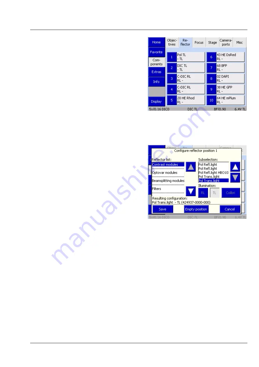
Reflector tab
Use the controls on this tab to configure the
reflector turret.
The tab shows up to ten buttons, depending on
the actual number of objective mounts on the
nosepiece. The number of turret positions is
detected by the system during initialization (and on
activation of the
Settings
-
Components
page).
Before any reflectors have been configured, the
buttons are labeled only with the numbers of the
turret positions.
After a reflector position has been allocated, the
following data is displayed: Designation (Type),
Reflected-light module (RL), Transmitted-light
position / module (TL).
•
Press the relevant button to configure a turret
position.
•
Choose the respective reflector from the list in
the
Configure reflector position #
popup
window. The current selection is displayed in
the
Resulting Configuration
line.
•
Press the button for
RL
and/or
TL
, as
appropriate.
•
Press the
Save
button.
If the turret position has already been
configured, a confirmation prompt will appear.
The type of module can first be selected from the
reflector list:
−
Contrast module
−
Optovar
−
Beam splitter
−
Filter
−
Fluorescence filter set
Under
Contrast modules
and
Optovars
, the selection can subsequently be specified via the
subselection options provided on the right-hand side.
The same applies for
Beam splitter
. Please note that additional laser safety functions are activated when
LSM components are selected. For more details, see the LSM Operator Instructions.
Empty modules and RGB modules can be found in the
Filter
list. RGB filters are used, for example, when
color images are to be generated with a monochrome camera via the multi-channel image recording
module within the Axio Vision software. This option is used exclusively in transmitted light.
Fig. 132
Microscope -> Config ->
Components -> Reflector
Fig. 133
Configuring the reflector position


