


Zaxcom Fusion User’s Manual_____________________________________________________Chapter 10
157
Chapter 10
– Connector Pinouts
This section provides the pinouts for the connectors on the Fusion. The mating cable connector part number is
also provided for the less common connectors.
NOTE:
All of the diagrams in this chapter show the solder side of each connector.
Power Connector
The Power Connector on the Fusion is a standard 4-pin XLR connector (A4F) available at most electronics stores.
The Fusion requires a power source of 9.5 to 18 VDC @ 1 A.
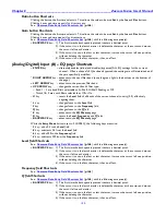
3 2
4 1
Figure 10-1 XLR-4F Power Connector Pin Numbering
Pin
Description
1
Ground
2
Ground
3
Output: +12 VDC
4
Input: 9.5 to 18 VDC (+)
Table 10-1 XLR-4F Pin Description
Audio Input/Output Connectors, XLR-3
When building an analog cable, use balanced XLR cable.
3 3
1 2 2 1
Figure 10-2 XLR-3M (Left) and XLR-3F (Right) Audio Input & Output Connector Pin Numbering
Pin
Description
Pin
Description
Pin
Description
1
Ground (
X
)
2
(+) / Hot (
L
)
3
(
–
) / Cold (
R
)
Table 10-2 XLR-3 Pin Description