


FORM 150.75-NM2
9
YORK INTERNATIONAL
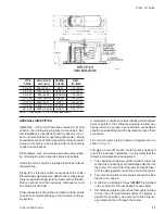
DIMENSIONS
CAUTION
FAILURE TO HEED FOLLOWING RECOMMENDED CLEARANCES MAY RESULT IN REDUCED SYSTEM
PERFORMANCE, NUISANCE SHUTDOWNS, AND SERVICE PROBLEMS.
LD01912
NOTES:
1. Clearances Minimum YORK required clearances to prevent condenser air recirculation and faulty operation of units are as follows:
Side to wall 8'0"* Rear to wall 8'0"* Control Panel End to wall 5'0"* Top 50'0" Distance between adjacent units 12'
0"
* No more than one wall can be higher than the top of the unit. The aread within the claearnaces shown above and area under the unit
must be kept clear of all obstructions that would impede free air flow to the unit. In installations where winter operation is intended and
snow accumilations are expected, additional unit height must be provided to insure full air flow.
2. Cooler liquid connection sizes (inlet and outlet) 8" victaulic for the YDAJ87KU6 YDAJ99MW9.
3. Dimensions are in inches. Drawings are not to scale and are for planning purposes only. Contact nearest YORK office for detail drawings.
4. Modeules have 1-1/8" of space between to facilitate maintenance.
5. Spring isolators (OPTIONAL) will increase overall height of unit by approx. 6". Refer to FORM 150.40-ES3 for details.
6. Be sure to review WARNINGS on page 2 prior to installation.
WEIGHT DISTRIBUTION (LB.)
DIM.
MODEL YDA
A
B
C
D
E
F
G
H
J
J87HU7
1953
1992
2010
2285
1947
2129
2147
2228
1'6"
J87KU6
1954
1995
2013
2287
1956
2141
2159
2236
1'5"
J97KU7
1971
2018
2034
2312
2023
2235
2251
2317
1'6"
J88MU6, J98MU7
1973
2020
2036
2314
2030
2245
2261
2324
1'6-1/2"
J99MW6, J99MU7
2094
2141
2157
2440
2113
2328
2370
2418
1'6-1/2"
J99MW9
2162
2209
2225
2508
2181
2397
2439
2486
1'6-1/2"
Содержание YDAJ87HU7
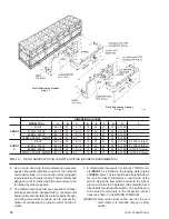
Страница 4: ...YORK INTERNATIONAL 4 FIG 1 UNIT COMPONENTS Typical on each of the two modules 00023TG 00024TG...
Страница 5: ...FORM 150 75 NM2 5 YORK INTERNATIONAL FIG 1 UNIT COMPONENTS Cont d LD01910 00025TG...
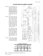
Страница 24: ...YORK INTERNATIONAL 24 MASTER MODULE WIRING DIAGRAM LD01933 FIG 17 MASTER MODULE CONNECTION DIAGRAM...
Страница 30: ...YORK INTERNATIONAL 30 SLAVE MODULE WIRING DIAGRAM FIG 20 SLAVE MODULE CONNECTION DIAGRAM LD01941...
Страница 99: ...FORM 150 75 NM2 99 YORK INTERNATIONAL...