


YORK INTERNATIONAL
18
5. As an aid to servicing, thermometers and pressure
gauges should be installed in each of the inlet and
outlet water lines. One connection piont (plugged)
is provided in each cooler nozzle. Thermometers and
gauges are not furnished with the unit and are to be
furnished by other suppliers.
6. The chilled liquid lines that are exposed to outdoor
ambients should be wrapped with a supplemental
heater cable and insulated to protect against freeze-
up during low ambient periods, and to prevent for-
mation of condensation on lines in warm humid cli-
mates.
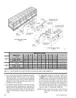
7. A chilled water flow switch, (either by YORK or oth-
ers)
MUST
be installed in the leaving water piping
of
EACH
cooler. There should be a straight horizon-
tal run of at least 5 diameters on each side of the
switch. Adjust the flow switch paddle to the size of
pipe in which it is to be installed. (See manufactuers
instructions furnished with switch). The switches are
to be wired to terminals in the respective control
panel as shown in the WIRING DIAGRAM.
WARNING: Flow switch must not be used to stop and
start chiller. It is intended only as a safety
switch.
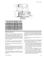
LD01923
DIMENSIONS - INCHES
MODEL YDAJ
A
B
C
D
E
F
G
H
J
, 87HU7
188-1/4
93
18-1/2
15
24
25
20
6-150#
ARRGT.
87KU6, 97KU7
188-1/4
93
18-1/2
15
24
25
20
6-150#
1
88MU6, 98KU7
188-1/4
93
18-1/2
15
24
25
20
8-150#
99MW6, 99MU7, 99MW9 188-1/4
84
24
19
30
33
26
8-150#
, 87HU7
188-1/4
93
18-1/2
15
24
25
26
6-150#
8-150# or larger
ARRGT.
87KU6, 97KU7
188-1/4
93
18-1/2
15
24
25
26
6-150#
8-150# or larger
2
88MU6, 98KU7
188-1/4
93
18-1/2
15
24
25
26
8-150# 10-150# or larger
99MW6, 99MU7, 99MW9 188-1/4
84
24
19
30
33
30
8-150# 10-150# or larger
FIG. 13
FIELD FABRICATED CHILLED WATER PIPING (HEADER ARRANGEMENTS)
Field Fabricates Header
Arrgt. 1
Field Fabricates Header
Arrgt. 2
Содержание YDAJ87HU7
Страница 4: ...YORK INTERNATIONAL 4 FIG 1 UNIT COMPONENTS Typical on each of the two modules 00023TG 00024TG...
Страница 5: ...FORM 150 75 NM2 5 YORK INTERNATIONAL FIG 1 UNIT COMPONENTS Cont d LD01910 00025TG...
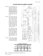
Страница 24: ...YORK INTERNATIONAL 24 MASTER MODULE WIRING DIAGRAM LD01933 FIG 17 MASTER MODULE CONNECTION DIAGRAM...
Страница 30: ...YORK INTERNATIONAL 30 SLAVE MODULE WIRING DIAGRAM FIG 20 SLAVE MODULE CONNECTION DIAGRAM LD01941...
Страница 99: ...FORM 150 75 NM2 99 YORK INTERNATIONAL...