


YORK INTERNATIONAL
80
CHECKING SUPERHEAT AND SUBCOOLING
The subcooling should always be checked when charg-
ing the system with refrigerant and/or before setting the
superheat.
When the refrigerant charge is correct, there will be no
bubbles in the liquid sightglass with the system operat-
ing under full load conditions, and there will be 10°F to
15°F subcooled liquid refrigerant leaving the condenser.
An overcharged system should be guarded against. Evi-
dences of overcharge are as follows:
a. If a system is overcharged, the discharge pressure
will be higher than normal. (Normal discharge/con-
densing pressure can be found in refrigerant tem-
perature/pressure chart; use entering air tempera-
ture +30°F for normal condensing temperatures).
b. The temperature of the liquid refrigerant out of the
condenser should not be more than 15°F less than
the condensing temperature. (The temperature cor-
responding to the condensing pressure from refrig-
erant temperature/pressure chart).
The subcooling temperature should be taken by record-
ing the temperature of the liquid line at the outlet of the
condenser and recording the liquid line pressure at the
liquid stop valve and converting it to a temperature from
the temperature/pressure chart.
Example:
LIQUID LINE PRESSURE
202 PSIG converted to
102°F
Minus Liquid Line Temperature
-90°F
Subcooling =
12°F
Record:
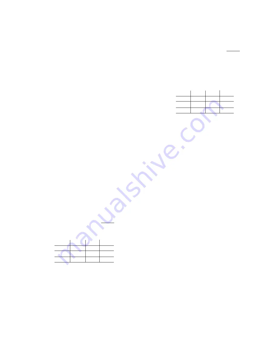
SYS 1 SYS 2 SYS 3 SYS 4
Liquid Line Press:
PSIG
Liquid Line Temp:
°F
Subcooling:
°F
After the subcooling is set at 10°-15°F the superheat
should be checked.
The superheat should be checked only after steady op-
eration of the chiller has been established, the leaving
chilled liquid has been pulled down to the required tem-
perature, and the unit is running fully loaded. Correct
superheat setting is 12°-15°F.
The superheat is the difference between the actual tem-
perature of the returned refrigerant gas entering the
compressor and the temperature corresponding to the
suction pressure as shown in a standard pressure/tem-
perature chart.
Example:
Suction Temperature
46°F
Minus Suction Pressure 60 PSIG
Converted to Temperature
- 34°F
Superheat
12°F
The suction temperature should be taken 6" before the
compressor service valve, and the suction pressure is
taken at the compressor suction service valve.
Record:
SYS 1 SYS 2 SYS 3 SYS 4
Suction Temperature:
°F
Suction Pressure:
PSIG
Superheat:
°F
Normally, the thermal expansion valve need not be ad-
justed in the field. If, however, an adjustment is to be
made, the expansion valve adjusting screw should be
turned not more than one turn at a time, allowing suffi-
cient time (approximately 15 minutes) between adjust-
ments for the system and the thermal expansion valve
to respond and return to settled operation.
If the unit has been functioning satisfactorily during the
initial operating period, it is ready for continuous opera-
tion.
¨
Leak check compressors, fittings, and piping to as-
sure no leaks are present from improper handling.
NOTES:______________________________________
______________________________________________________
______________________________________________________
______________________________________________________
______________________________________________________
______________________________________________________
______________________________________________________
______________________________________________________
______________________________________________________
______________________________________________________
______________________________________________________
______________________________________________________
¨
Start-Up Complete
Содержание YDAJ87HU7
Страница 4: ...YORK INTERNATIONAL 4 FIG 1 UNIT COMPONENTS Typical on each of the two modules 00023TG 00024TG...
Страница 5: ...FORM 150 75 NM2 5 YORK INTERNATIONAL FIG 1 UNIT COMPONENTS Cont d LD01910 00025TG...
Страница 24: ...YORK INTERNATIONAL 24 MASTER MODULE WIRING DIAGRAM LD01933 FIG 17 MASTER MODULE CONNECTION DIAGRAM...
Страница 30: ...YORK INTERNATIONAL 30 SLAVE MODULE WIRING DIAGRAM FIG 20 SLAVE MODULE CONNECTION DIAGRAM LD01941...
Страница 99: ...FORM 150 75 NM2 99 YORK INTERNATIONAL...