


FORM 150.75-NM2
27
YORK INTERNATIONAL
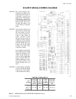
SLAVE MODULE WIRING DIAGRAM
FIG. 18
SLAVE MODULE ELEMENTARY DIAGRAM (Contd)
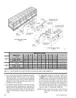
CAUTION: No Controls (relays, etc.)
should be mounted in the
Smart Panel enclosure or
connected to power sup-
plies in the control panel.
Additionally, control wiring
not connected to the Smart
Panel should not be run
through the cabinet. This
could result in nuisance
faults.
CAUTION: Any inductive devices (re-
lays) wired in series with
the flow switch for start/
stop, into the Alarm cir-
cuitry, or pilot relays for
pump starters wired
through motor contactor
auxiliary contacts must be
suppressed with YORK P/
N 031-00808-000 sup-
pressor across the relay/
contactor coil which acti-
vates the contacts.
Any contacts connected to
flow switch inputs or BAS
inputs on terminals 13-19
of TB3, or any other termi-
nals, must be suppressed
with a YORK P/N 031-
00808-000 suppressor
across the relay/contactor
coil which activates the
contacts.
CAUTION: Control wiring connected
to the control panel should
never be run in the same
conduit with power wiring.
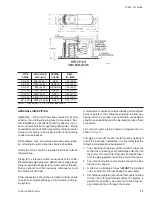
CONTROL
MIN
MAX
NON-FUSED
UNIT
POWER
CIRCUIT
DUAL
DISC. SW.
VOLTAGE
SUPPLY
AMPACITY
ELEMENT
SIZE
FUSE SIZE
All
Models w/o 115-1-50/60
20A
20A, 250A
30A, 240A
Transformers
CONTROL POWER SUPPLY
LD01936
Содержание YDAJ87HU7
Страница 4: ...YORK INTERNATIONAL 4 FIG 1 UNIT COMPONENTS Typical on each of the two modules 00023TG 00024TG...
Страница 5: ...FORM 150 75 NM2 5 YORK INTERNATIONAL FIG 1 UNIT COMPONENTS Cont d LD01910 00025TG...
Страница 24: ...YORK INTERNATIONAL 24 MASTER MODULE WIRING DIAGRAM LD01933 FIG 17 MASTER MODULE CONNECTION DIAGRAM...
Страница 30: ...YORK INTERNATIONAL 30 SLAVE MODULE WIRING DIAGRAM FIG 20 SLAVE MODULE CONNECTION DIAGRAM LD01941...
Страница 99: ...FORM 150 75 NM2 99 YORK INTERNATIONAL...