


FORM 150.75-NM2
13
YORK INTERNATIONAL
For ground level installations, precautions should be taken
to protect the unit from tampering by or injury to unau-
thorized persons. Screws and / or latches on access
panels will prevent casual tampering. However, further
safety precautions such as a fenced-in enclosure or lock-
ing devices on the panels may be advisable. A tamperproof
kit is available as an option. Check local authorities for
safety regulations.
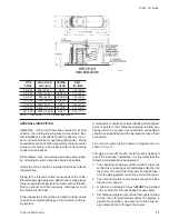
Rooftop Locations
Choose a spot with adequate structural strength to safely
support the entire weight of the unit and service per-
sonnel. Care must be taken not to damage the roof.
Consult the building contractor or architect if the roof is
bonded. Roof installations should have wooden beams
(treated to reduce deterioration), cork, rubber or vibra-
tion isolators under the base to minimize vibration.
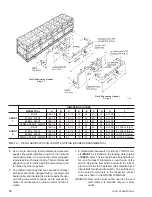
SHIPPING BRACES
Two shipping brackets (typically galvanized steel) which
run diagonally along each side of each module, must
be removed once the unit is mounted on its foundaiton.
A third bracket on the right rear of the unit should also
be removed. This bracket runs across the bottom right
corner of the unit behind the compressors.
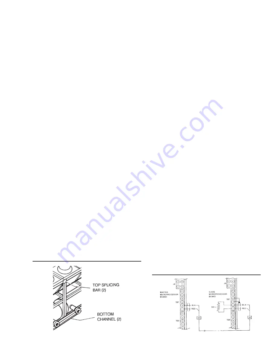
MODULAR INSTALLATION
All chillers require a Splicing Kit to connect the two
modules together. This will be field mounted. See Fig.
5). For mounting top slicing bar, loosen eight (8) exist-
ing nuts at top end of frame of both modules. Secure
top slicing bars in place, using existing nuts and bolts.
Mount bottom channel bars on both sides by loosening
eight (8) existing nuts at the bottom end channels. Se-
cure bars in place, using existing nuts and bolts. The
Splicing Kit will be shipped in a separate box.
COMMUNICATIONS LINK INSTALLATION
An RS-485 communications link MUST be connected
between the Master and the Slave Control Panels. One
of two installation procedures will be required, depend-
ing upon when the chiller was manufactured. Please
read the note below before proceeding.
NOTES: In the fall / winter of 1995, a design change
will be implemented in the communications link
to add transient protection circuit boards (LTP,
Lan Transient Protection) to the RS-485 com-
munications link. These boards are designed
to protect the RS-485 drivers on the Micro
Boards from severe RFI transients that may
enter through earth ground and cause a cir-
cuitry failure and subsequent communications
loss on chillers that have been in service.
There is no need to worry if the boards are
not included with the chiller. The boards are
designed with the intent of being used where
communications links are hundreds or thou-
sands of feet long. The circuits are being
added as a precaution / enhancement. No
prior history of failures exists on 3 and 4 com-
pressor chillers with communications between
two micropanels within the chiller. NO RET-
ROFIT IS NECESSARY!
To determine whether to follow installation pro-
cedure #1 or #2, open the control panel of the
Slave Panel and inspect the TB7 connector
on the Micro Board. If a transient Protection
Circuit board is installed, (Fig. 7A), use Pro-
cedure #2. Otherwise use Procedure #1.
Procedure #1
The 2-wire shielded cable should be connected between
TB7 of the Master and TB7 of the Slave Micro Board as
shown in Fig. 6. This cable is shipped rolled up in the
Slave Panel. Connection points to each Microproces-
sor are shown in Fig. 6. Also assure that the shield and
the 180W resistor are connected at the Slave Panels
shown in Fig. 6. Place a wire jumper between TB7-3 &
TB7-4 as shown in Fig. 6.
NOTE: DO NOT connect the shield at the MASTER
Microboard.
Cable routing should be through existing cable entry in
the bottom of the Control Panels and should follow the
center condenser support the entire length of the chiller.
FIG. 5
SPLICING KIT
FIG. 6
RS-485 WIRING CONNECTION
LD01914
LD01913
Содержание YDAJ87HU7
Страница 4: ...YORK INTERNATIONAL 4 FIG 1 UNIT COMPONENTS Typical on each of the two modules 00023TG 00024TG...
Страница 5: ...FORM 150 75 NM2 5 YORK INTERNATIONAL FIG 1 UNIT COMPONENTS Cont d LD01910 00025TG...
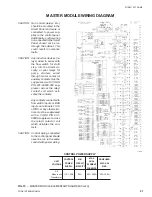
Страница 24: ...YORK INTERNATIONAL 24 MASTER MODULE WIRING DIAGRAM LD01933 FIG 17 MASTER MODULE CONNECTION DIAGRAM...
Страница 30: ...YORK INTERNATIONAL 30 SLAVE MODULE WIRING DIAGRAM FIG 20 SLAVE MODULE CONNECTION DIAGRAM LD01941...
Страница 99: ...FORM 150 75 NM2 99 YORK INTERNATIONAL...