FORM 150.75-NM2
11
YORK INTERNATIONAL
NOTES:
1. Minimum Circuit Ampacity (MCA) is based on 125% of the rated load amps for the largest motor plus 100% of the rated load amps for all
other loads included in the circuit, per N.E.C. Article 430-24. If Factory Mounted Control Transformer is provided, add the following to the
system MCA values in the Tables: -17, add 10 amps; -28, add 9 amps; -40, add 6 amps; -46, add 5 amps; -58, add 4 amps.
2. Minimum fuse size is based on 150% of the rated load amps for the; largest motor plus 100% of the rated load amps for all other loads
included in the circuit, per U.L. Standard 1995, Section 1995, Section 36.1. It is not recommended in all applications where brown outs,
frequent starting and stopping of the unit and/or operation at ambient temperatures in excess of 95°F is anticipated.
3. Maximum fuse size is based on 225% of the rated load amps for the largest motor plus 100% of the rated load amps for all other loads
included in the circuit, per N.E.C. Article 440-12A1.
4. The recommended disconnect switch is based on 115% of the rated load amps for all the loads included in the circuit, per U.L. 1995, Fig. 36.2.
5. HACR-Type circuit breakers are UL-listed circuit breakers that have been found suitable for use with heating, air conditioning and refrigeration
equipment comprising multimotor or combination loads and are marked Listed HACR-Type, refer to N.E.C. Article 440-21. Maximum HACR
circuit breaker rating is based on 225% of the rated load amps for the largest motor plus 100% of the rated load amps for all other loads
included in the circuit, per UL 1995, Fig. 36.2. Canadian and international models may not require HACR-Type circuit breakers.
6. The INCOMING WIRE RANGE is the minimum and maximum wire size that can be accommodated by unit wiring lugs. The (1), (2), (3)
or (4) preceding the wire range indicates the number of termination points available per phase of the wire range specified. The (1-2), (1-
3), or (1-4) preceding the wire range indicates that a single multi-termination lug is available per phase that can accept from two (1-2) to
four (1-4) wires of the wire range specified. (1) #1-600MCM or (2) #1-250MCM indicates that a single lug is supplied and it will accept a
single wire up to 600MCM or 2 wires up to 250MCM. Actual wire size and number of wires per phase must be determined based on
ampacity and job requirements using N.E.C. wire sizing information. The above recommendations are based on the National Electric
Code and using copper connectors only. Field wiring must also comply with local codes.
7. A ground lug is provided for each compressor system to accommodate field grounding conductor per N.E.C. Article 250-54. A control
circuit grounding lug is also supplied. Incoming ground wire range is #6 - #2/0.
8. The supplied disconnect is a Disconnection Means as defined in N.E.C. Article 100.B, and is intended for isolating the unit from the
available power supply to perform maintenance and troubleshooting. This disconnect is not intended to be a Load Break Device.
9. All unit compressors have a part winding electrical configuration such that the indicated Locked Rotor Amps are Part Wind Locked Rotor Amps.
VOLTAGE CODE
17
=
200-3-60 Hz
28
=
230-3-60 Hz
40
=
380-3-60 Hz
46
=
460-3-60 Hz
50
=
380/415-3-50 Hz
58
=
575-3-60 Hz
64
=
346-3-50 Hz
LEGEND:
VOLT
= Voltage
MCA
= Minimum Circuit Ampacity
DISC
= Disconnect
N/A
= Not Available
CPR-RLA
= Compressor Running Load Amps
CRP-LRA
= Compressor Part Winding Inrush Amps
FLA
= Full Load Amps
CKT BRK
= Circuit Breaker
HACR
= Heating, Air Conditioning and Refrigeration
CONTROL POWER SUPPLY
UNIT
CONTROL
MIN CIRCUIT
MAX DUAL
NON-FUSED
VOLTAGE
POWER SUPPLY
AMPACITY
ELEMENT FUSE SIZE
DISC. SW. SIZE
Std. Models w/o Transformers
115-1-50/60
20A
20A, 250V
30A, 240V
SYSTEM 1 OR 3
SYSTEM 2 OR 4
LOAD RATINGS
LOAD RATINGS
MODEL
VOLTAGE
CPR
CPR
FAN
CPR
CPR
FAN
YDA
CODE
LRA
9
RLA
RLA
LRA
9
RLA
RLA
EA
EA
J87HU7
-50
585
170
5.9
585
150
5.9
J87HU7
-64
668
187
5.8
668
165
5.8
J87KU6
-17
1322
403
10
1322
352
10
J87KU6
-28
1150
350
12
1150
306
12
J87KU6
-40
696
212
5.2
696
185
5.2
J87KU6
-46
575
175
5
575
153
5
J97KU7
-50
760
195
5.9
585
150
5.9
J87KU6
-58
460
140
4.9
460
122
4.9
J97KU7
-64
917
214
5.8
668
165
5.8
J88MU6
-17
1322
403
10
1322
403
10
J88MU6
-28
1150
350
12
1150
350
12
J88MU6
-40
696
212
5.2
696
212
5.2
J88MU6
-46
575
175
5
575
175
5
J98MU7
-50
760
198
5.9
585
170
5.9
J88MU6
-58
460
140
4.9
460
140
4.9
J98MU7
-64
917
217
5.8
668
187
5.8
J99MU7
-50
760
198
5.9
760
198
5.9
J99MU7
-64
917
217
5.8
917
217
5.8
J99MW6
-40
997
254
5.2
997
254
12
J99MW6
-46
830
210
5
830
210
5.2
J99MW6
-58
664
168
4.9
664
168
4.9
J99MW9
-50
760
198
9.7
760
198
9.7
J99MW9
-64
917
217
9.2
917
217
9.2
Содержание YDAJ87HU7
Страница 4: ...YORK INTERNATIONAL 4 FIG 1 UNIT COMPONENTS Typical on each of the two modules 00023TG 00024TG...
Страница 5: ...FORM 150 75 NM2 5 YORK INTERNATIONAL FIG 1 UNIT COMPONENTS Cont d LD01910 00025TG...
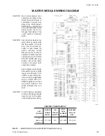
Страница 24: ...YORK INTERNATIONAL 24 MASTER MODULE WIRING DIAGRAM LD01933 FIG 17 MASTER MODULE CONNECTION DIAGRAM...
Страница 30: ...YORK INTERNATIONAL 30 SLAVE MODULE WIRING DIAGRAM FIG 20 SLAVE MODULE CONNECTION DIAGRAM LD01941...
Страница 99: ...FORM 150 75 NM2 99 YORK INTERNATIONAL...


