


FORM 150.75-NM2
73
YORK INTERNATIONAL
as possible. Additionally, the lag system will automati-
cally become the lead anytime the system switch on
the Microprocessor Board of the compressor currently
in the lead is placed in the OFF position. This is also
done to maintain water temperature as close to setpoint
as possible.
If MANUAL Lead/Lag is selected, an external dry con-
tact (switch) must be wired into each Control Panel. This
contact is supplied by others. When the contact is
closed, SYS 2 will be the lead system. With the contact
open, SYS 1 is the lead.
Manual Lead/Lag selection can be automatically over-
ridden by the micro to allow the lag compressor to auto-
matically become the lead, anytime the selected lead
compressor shuts down due to a safety threshold be-
ing exceeded. This is done to try to maintain water tem-
perature as close to setpoint as possible. No lead/lag
switchover will take place if the system switch of the
Microprocessor of the lead compressor is placed in the
OFF position.
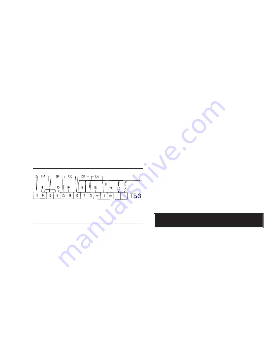
The dry contact for manual lead/lag selection is wired
into terminals 13 and 19. The location of these contacts
is shown below in Fig. 33.
FIG. 33
LEAD/LAG CONTACT CONNECTION LO-
CATION
NOTE: It is advisable to select the same type of LEAD/
LAG control on both the Master and Slave
Microprocessor Boards.
MEMORY BATTERY BACK-UP
Each Microprocessor Board contains a Real Time Clock
(RTC) I.C. Chip with an internal battery back-up. The
battery back-up assures that any programmed values,
clock, all fault information, accumulated information
such as starts/run time, etc. stored in the RTC memory
is not lost when a power failure occurs regardless of
the time period.
The battery is a 10-year lithium type. The life of the bat-
tery with power removed will depend upon whether the
Real Time Clocks internal clock circuit is energized.
With the clock OFF, approximately 10 years can be ex-
pected, with the clock ON, approximately 5 years.
The clock is turned ON and OFF by a jumper on the
Microprocessor Board. While a chiller is operating, the
clock must be ON. Otherwise the internal clock on the
microprocessor will not be active and the micro cannot
keep track of time, although all other functions will op-
erate normally. This could result in the chiller not start-
ing due to the time frozen on the clock falling outside
the START/STOP time window that is programmed in
the DAILY SCHEDULE.
If the chiller is shut-down for extended periods of
months, it may be desirable to disable the clock to save
battery life. The clock can then be reactivated and re-
programmed when the chiller is returned to service.
NOTE: ALL PROGRAMMED VALUES AND STORED
DATA, OTHER THAN THE INTERNAL CLOCK
TIME-KEEPING, WILL BE MAINTAINED IN
MEMORY REGARDLESS OF WHETHER THE
CLOCK IS ON OR OFF AND REGARDLESS
OF THE LENGTH OF THE POWER FAILURE.
To disable the clock, place the jumper (Fig. 43, Page
74) in the OFF position. To activate it, place the jumper
in the ON position.
On power-up, the microprocessor will check the Real
Time Clock (RTC Chip) battery to assure that the inter-
nal battery is still operational. This is accomplished by
performing an RTC RAM location check. As long as the
battery checks out, the microprocessor will continue on
with business without interruption.
If a check is made and the battery has failed, the micro-
processor will not allow the chiller to run and the follow-
ing STATUS message will appear:
The only way to run the chiller is to press the MANUAL
OVERRIDE key. Under low battery conditions, the
manual override key will function differently than it nor-
mally does in service situations where it overrides the
daily schedule for only 30 min. In a low battery condi-
tion, the MANUAL OVERRIDE key will zero out the daily
schedule to allow unlimited operation regardless of the
time on the internal clock. Default values will also be
loaded into memory for all setpoints and cut-outs. These
may require reprogramming to assure they meet chiller
operating requirements. In addition, the low battery mes-
sage which is displayed for this condition will disappear.
NOTE: If a power failure should again occur, the above
process will again need to be repeated to bring
the chiller back on line.
In the unlikely event the low battery message should
ever appear, it will require the RTC Chip U13 on the
Microprocessor Board (Fig. 25) to be replaced. Care
should be taken to assure that the chip is properly in-
! !
W A R N I N G
! !
! !
L O W
B A T T E R Y
! !
LD01946
Содержание YDAJ87HU7
Страница 4: ...YORK INTERNATIONAL 4 FIG 1 UNIT COMPONENTS Typical on each of the two modules 00023TG 00024TG...
Страница 5: ...FORM 150 75 NM2 5 YORK INTERNATIONAL FIG 1 UNIT COMPONENTS Cont d LD01910 00025TG...
Страница 24: ...YORK INTERNATIONAL 24 MASTER MODULE WIRING DIAGRAM LD01933 FIG 17 MASTER MODULE CONNECTION DIAGRAM...
Страница 30: ...YORK INTERNATIONAL 30 SLAVE MODULE WIRING DIAGRAM FIG 20 SLAVE MODULE CONNECTION DIAGRAM LD01941...
Страница 99: ...FORM 150 75 NM2 99 YORK INTERNATIONAL...