IM 701240-02E
Front Panel Parts and Functions
This section describes the names and functions of the keys and knobs on the SL1400 front panel. For details on each item,
see the respective chapter or section in the user's manual indicated by the mark.
CH
MENU
DISPLAY
MODE
ESC
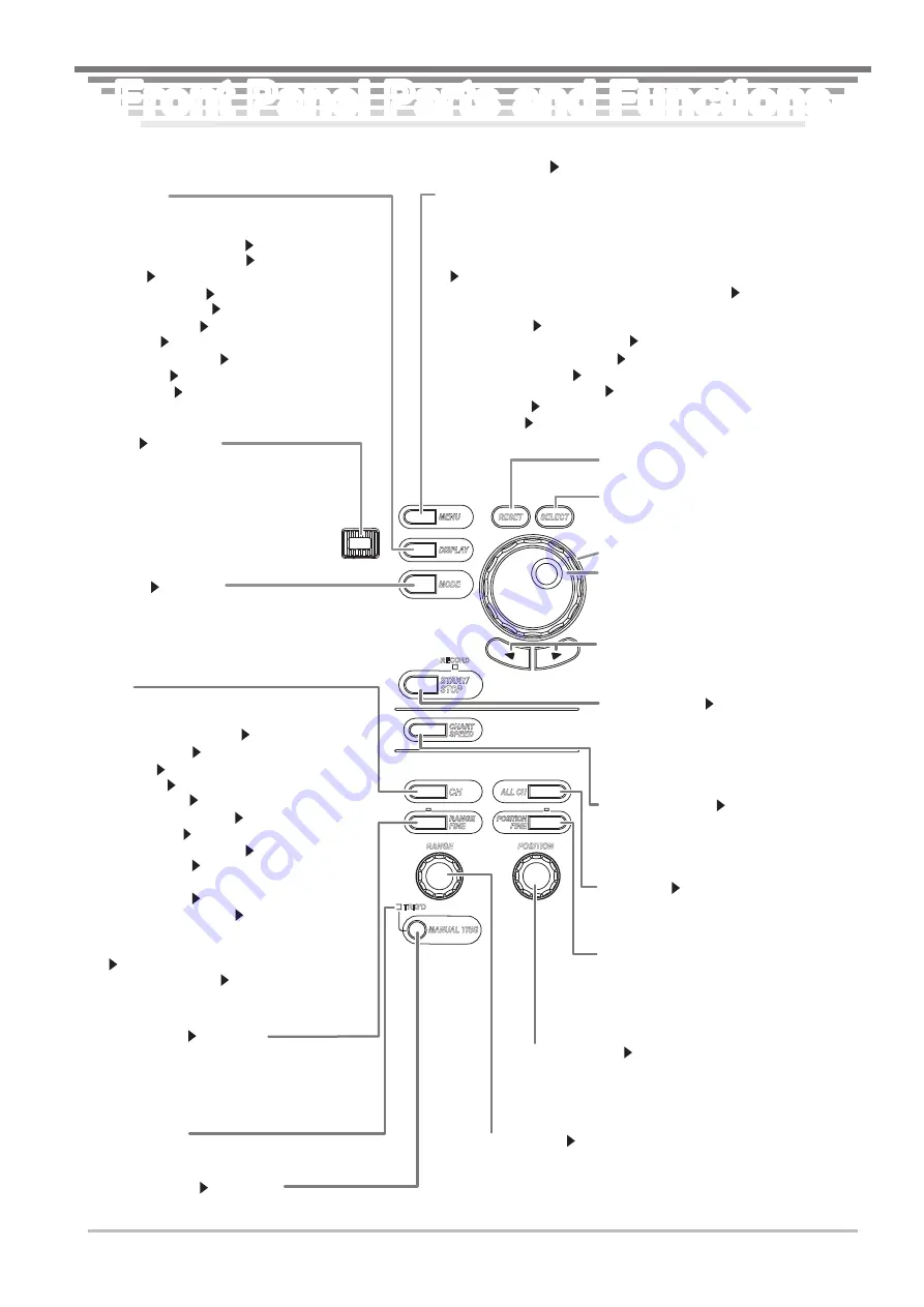
ESC key
Section 8.13
Used to clear the menu. Returns to the previous
menu if menus are overlapped. When a menu is
cleared using the ESC key, the channel
information appears. If you press the ESC key
again, the channel information is cleared, and the
waveform display area is expanded horizontally.
MODE key
Section 9.1
Displays a menu used to select the recorder mode. Three
modes are available: Memory, Chart Recorder, and X-Y
Recorder.
MENU key
Displays the setup menu indicated below. The displayed menu varies depending
on the recorder mode selected using the MODE key menu.
• Measurement conditions such as the record time, sample rate, time base, and
waveform acquisition mode
Sections 5.2, 5.20, 7.2, 7.3, and 7.5
• Conditions for recording the data on the built-in printer Chapter 9
• Conditions for starting the acquisition such as the trigger mode, trigger position,
and trigger type Chapter 6
• Computing the acquired waveform Chapter 10
• Storing/Recalling the setup data Section 13.1
• Printing Screen Images Chapter 12
• Saving the screen image data Section 13.12 to 13.14
• Remote control Communication Interface User’s Manual
• Other settings Sections 3.6, 4.4 to 4.6, chapter 15, sections 16.1 to 16.4, and
sections 17.3 and 17.4
RESET
SELECT
RECORD
ALL CH
RANGE
POSITION
TRIG'D
MANUAL TRIG
START/
STOP
CHART
SPEED
RANGE
FINE
POSITION
FINE
DISPLAY key
Displays a menu related to the screen display shown
below.
• Display format and mapping Section 8.1
• Display interpolation method Section 8.2
• Graticule Section 8.3
• Accumulated display Section 8.4
• X-Y waveform display Section 8.6
• Translucent display Section 8.8
• Scale value Section 8.9
• Waveform label display Section 8.10
• Extra window Section 8.11
• Level indicator Section 8.12
RANGE FINE key
Section 5.8
Press the key to illuminate the indicator above the
key. In this condition, you can use the rotary knob to
zoom in or out of the vertical axis by specifying the
magnification (zoom rate).
MANUAL TRIG key
Section 6.19
Press the key to forcibly activate a trigger.
Trigger indicator
Illuminates when a trigger is activated.
Jog shuttle
Used to set values, move the cursor, and select
items in setup operations. Turn the shuttle ring to
vary the rate of change according to its angle.
Shuttle ring
SELECT key
Confirms the item selected or value set using the
jog shuttle.
RESET key
Resets the numeric value to the default value.
Arrow keys
Moves the selected digit when entering a value.
Used to change settings and move the cursor.
START/STOP key
Section 7.1
Starts/Stops waveform acquisition according to
the trigger mode. Waveform acquisition is in
progress when the RECORD indicator above the
key is illuminated.
CHART SPEED key
Section 9.2
This key is valid only when Chart Recorder mode
is selected with the MODE key. Press this key to
display a menu used to set the chart speed.
ALL CH key
Section 5.19
Displays a pop-up window containing a list of
settings similar to the channel key menu.
POSITION FINE key
Press the key to illuminate the indicator above
the key. In this condition, you can use the
position knob to set the vertical display position
of the waveform in 0.1-division resolution.
POSITION knob
Section 5.4
Sets the vertical display position of the waveform. You select
the target channel with the channel key menu before you turn
this knob.
RANGE knob
Section 5.3
Sets the voltage range. You select the target channel with the channel
key menu before you turn this knob. If you change the range when
waveform acquisition is stopped, the new range takes effect when you
restart the acquisition.
CH key
Displays a menu used to select the channel.
• If a channel between CH1 and CH16 is selected
• Channel display ON/OFF Section 5.1
• Vertical position Section 5.4
• Coupling Section 5.5
• Probe type Section 5.6
• Bandwidth limit Section 5.7
• Zoom in or out vertically Sections 5.8 and 5.9
• Linear scaling Section 5.11
• Inverted waveform display Section 5.12
• Waveform label Section 8.10
• If Logic A or Logic B is selected
• Vertical position Section 5.4
• Zoom in or out vertically Section 5.8
• Logic probe selection, input signal selection, bit
display ON/OFF, bit label, and bit display position
Section 5.18
• Logic waveform label Section 8.10
Front Panel Parts and Functions
Front Panel Parts and Functions


