C2-02
C2-01
0.20 s
<1>
0.20 s
<1>
C2-02
C2-01
0.20 s
<1>
0.20 s
<1>
FWD run
REV run
Output
frequency
<1> S-Curve characteristic at Decel Start/End is fixed to 0.20 s.
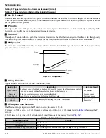
Figure 5.15 S-Curve Timing Diagram - FWD/REV Operation
Setting the S-curve will increase the acceleration and deceleration times.
Actual accel time = accel time s (C2-01 + C2-02) / 2
u
C4: Torque Compensation
The torque compensation function compensates for insufficient torque production at start-up or when a load is applied.
Note:
Set the motor parameters and V/f pattern properly before setting torque compensation parameters.
n
C4-01: Torque Compensation Gain
Sets the gain for the torque compensation function.
No.
Parameter Name
Setting Range
Default
C4-01
Torque Compensation Gain
0.00 to 2.50
1.00
Torque Compensation:
The drive calculates the motor primary voltage loss using the output current and the termination resistor value (E2-05) and
adjusts the output voltage to compensate insufficient torque at start or when load is applied. The effects of this voltage
compensation can be increased or decreased using parameter C4-01.
Adjustment
Although this parameter rarely needs to be changed, it may be necessary to adjust the torque compensation gain in small steps
of 0.05 in the following situations:
• Increase this setting when using a long motor cable.
• Decrease this setting when motor oscillation occurs.
Adjust C4-01 so the output current does not exceed the drive rated current.
u
C6: Carrier Frequency
n
C6-02: Carrier Frequency Selection
Sets the switching frequency of the drive output transistors. Changes to the switching frequency lower audible noise and reduce
leakage current.
Note:
Increasing the carrier frequency above the default value automatically lowers the drive current rating.
No.
Parameter Name
Setting Range
Default
C6-02
Carrier Frequency Selection
1 to A
Determined by o2-04
Settings:
C6-02
Carrier Frequency
1
2.0 kHz
2
5.0 kHz
3
8.0 kHz
4
10.0 kHz
5
12.5 kHz
C6-02
Carrier Frequency
6
15.0 kHz
7
Swing PWM 1
8
Swing PWM 2
9
Swing PWM 3
A
Swing PWM 4
Note:
Swing PWM uses a carrier frequency of 2.0 kHz as a base, then applies a special PWM pattern to reduce the audible noise.
5.4 C: Tuning
140
YASKAWA ELECTRIC SIEP YAIZ1B 01E YASKAWA AC Drive – Z1000 Bypass Technical Manual
Содержание Z1000 CIMR-ZU*A Series
Страница 54: ......
Страница 422: ...E 7 Fault Codes 422 YASKAWA ELECTRIC SIEP YAIZ1B 01E YASKAWA AC Drive Z1000 Bypass Technical Manual...
Страница 463: ...Index This Page Intentionally Blank YASKAWA ELECTRIC SIEP YAIZ1B 01E YASKAWA AC Drive Z1000 Bypass Technical Manual 463...
Страница 465: ......


