4. Control Panel and Display Description
4.1 Introduction
The control panel consists of a touch screen color LCD, LEDs and a power button. The LCD is on the
external side of the front door and the LEDs and the power button are on the internal side of the
front door. The audible alarm is also considered part of the control panel. Through the control
panel, a user can control the UPS operation, monitor all measured parameters, UPS battery
status/alarms and view or change settings.
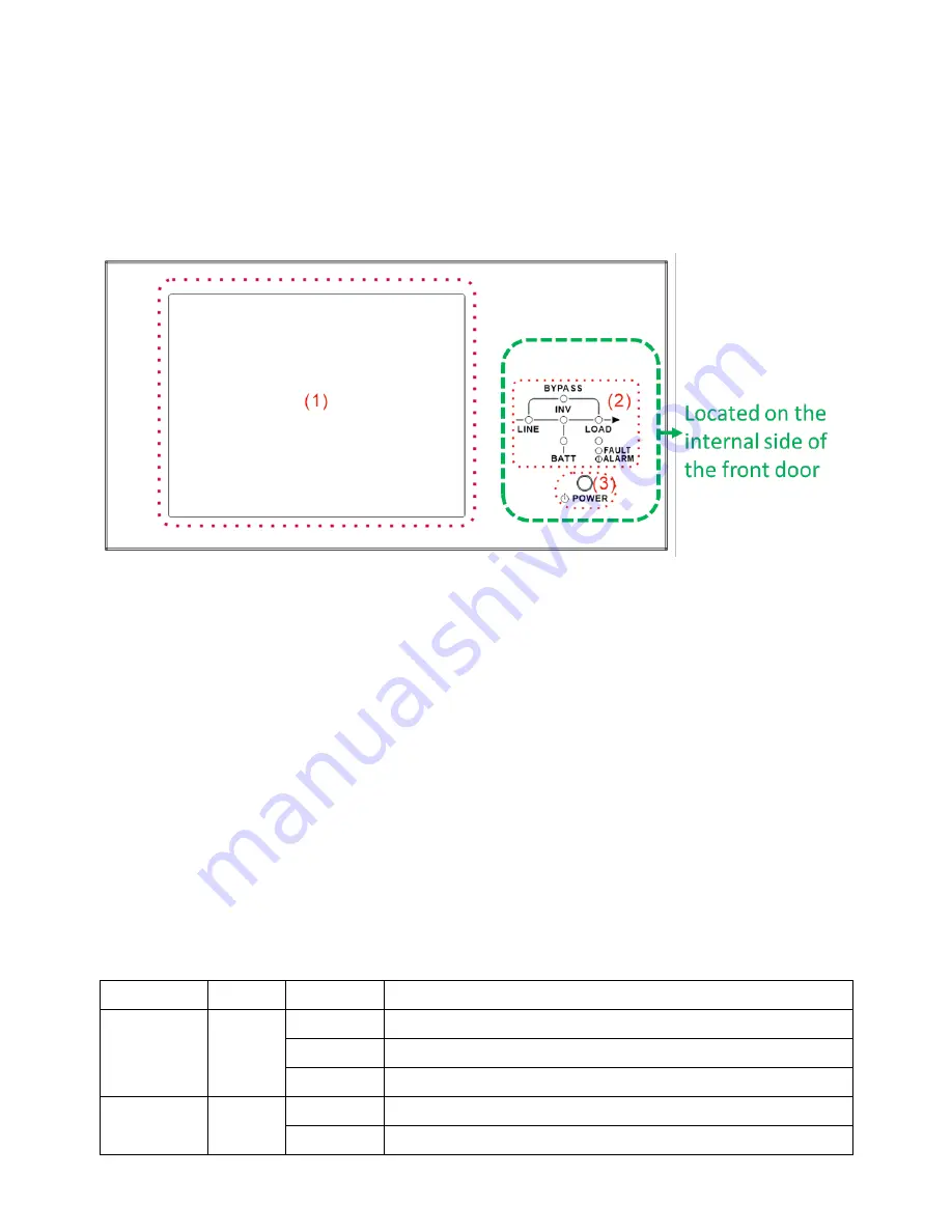
Figure 4-1 Control panel
(1)
LCD display: Graphic display of real-time UPS status and all
measured parameters.
(2)
LED indications. Refer to
Table 4-1
.
(3)
Power button. Refer to
Table 4-2
.
(4)
Audible Alarm. Refer to
Table 4-3
.
Table 4-1
: LED indications
LED
Color
Status
Definition
LINE
Green
On
Input source is normal.
Flashing
Main Input source is abnormal.
Off
No input source
BYPASS
Yellow
On
Load on Bypass
Flashing
Bypass Input source is abnormal.
Содержание X90-2S
Страница 10: ...2 5 UPS Cabinet Model X90 2S Drawing Cabinet Height 42U Monitor Module 1 Max Power Module 2 Max Power 140kVA...
Страница 12: ...2 6 1 Mechanical Data Dimensions Width Depth Height 600mm 1065m 2010mm Figure 2 8 Dimensions...
Страница 15: ...Figure 2 13 Terminal Blocks...
Страница 17: ...Off There is neither a fault nor an alarm...
Страница 22: ......
Страница 29: ...3 Operation Mode and UPS Operation 3 1 Block diagram of UPS Wiring diagram for dual inputs Figure 3 1...
Страница 37: ......
Страница 39: ...Step 7 Switch ON the output breaker Q3 AC startup procedure is complete...
Страница 42: ......
Страница 53: ...Figure 4 6 Control screen page...
Страница 55: ...Figure 4 9 System Measurement Screens...
Страница 56: ...Figure 4 10 Module Measurement Screens...
Страница 88: ......


