This delay timer will start counting after system
shutdown time has elapsed.
Power rating
setting
--
Set power rating value per module
⚫
50KVA
⚫
70KVA
Redundancy --
Set total power and redundancy
Redundancy: the QTY of redundant power module
MUST be set after UPS installation and after the
QTY of Power Modules is changed.
4.2.6.3 Setup-Battery Screen
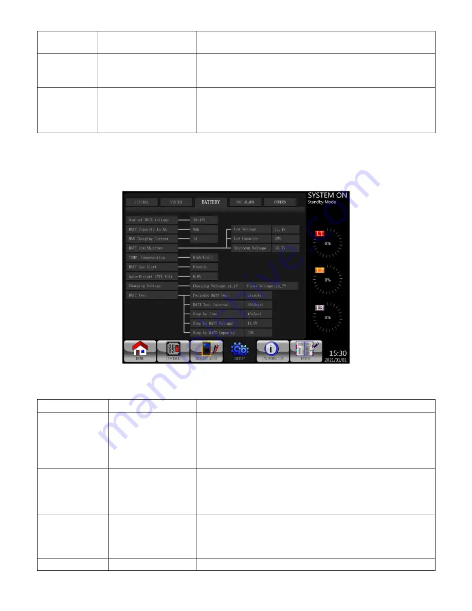
The Setup-Battery screen and setting list are shown in Figure 4-17 and table 4-9. Battery settings
can be changed only when UPS is operated in standby mode, otherwise, a warning screen will
appear as shown in Figure 4-16.
Figure 4-17 Setup-Battery Screen
Table 4-9
: Setup-Battery setting list
Setting Item
Sub Item
Explanation
Nominal
Battery Voltage
--
Set battery nominal voltage
⚫
16x12V (Default)
⚫
18x12V
⚫
20x12V
MUST be set after UPS installation.
Battery
Capacity in Ah --
Set battery capacity. (0~999)
⚫
9Ah (Default)
MUST be set after UPS installation or after
Battery capacity has been changed.
Maximum
Charging
Current
--
Set battery maximum charging current (1~128A)
1A (Default)
MUST be set after UPS installation or after
Battery capacity has been changed.
Battery Low/
Low Voltage
Set battery low voltage (10.5~11.5V)x(battery Number)
Содержание X90-2S
Страница 10: ...2 5 UPS Cabinet Model X90 2S Drawing Cabinet Height 42U Monitor Module 1 Max Power Module 2 Max Power 140kVA...
Страница 12: ...2 6 1 Mechanical Data Dimensions Width Depth Height 600mm 1065m 2010mm Figure 2 8 Dimensions...
Страница 15: ...Figure 2 13 Terminal Blocks...
Страница 17: ...Off There is neither a fault nor an alarm...
Страница 22: ......
Страница 29: ...3 Operation Mode and UPS Operation 3 1 Block diagram of UPS Wiring diagram for dual inputs Figure 3 1...
Страница 37: ......
Страница 39: ...Step 7 Switch ON the output breaker Q3 AC startup procedure is complete...
Страница 42: ......
Страница 53: ...Figure 4 6 Control screen page...
Страница 55: ...Figure 4 9 System Measurement Screens...
Страница 56: ...Figure 4 10 Module Measurement Screens...
Страница 88: ......


