


MAINTENANCE
Feed Chain Tension
4
4-10
25doc031016
MAINTENANCE
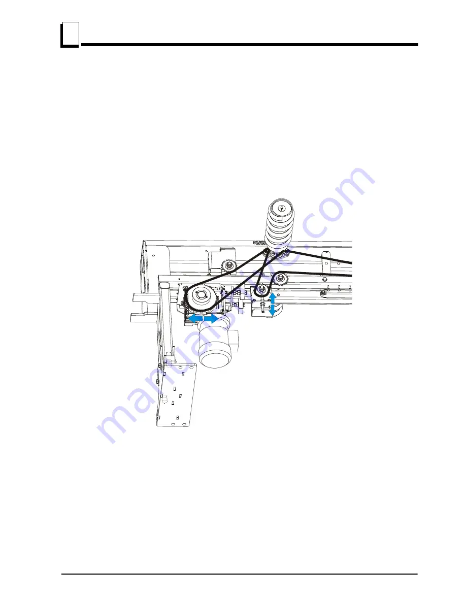
4.8
Feed Chain Tension
See Figure 4-17.
If necessary, use the adjustment bolts shown below to adjust the feed
chain tension.
CAUTION!
Do not overtension the chains of TVS tables,
Log Deck and Transfer Deck. Overtensioning may lead to
early failure of the gear, bearings, rollers and chains.
See Figure 4-18.
See the figure below for locations of the spiral rollers drive chains
tension adjustment bolts.
FIG. 4-19
Содержание TVS-FT Series
Страница 1: ......
Страница 2: ......
Страница 25: ...OPERATION TVS Setup Operation MHdoc031016 2 8 2 infeed table FIG 2 3 TVS SAW HEAD FIG 2 3 OUTFEED TABLE...
Страница 26: ...OPERATION TVS Setup 2 2 9 MHdoc031016 Operation FIG 2 3 ADDITIONAL INFEED TABLE...