background image

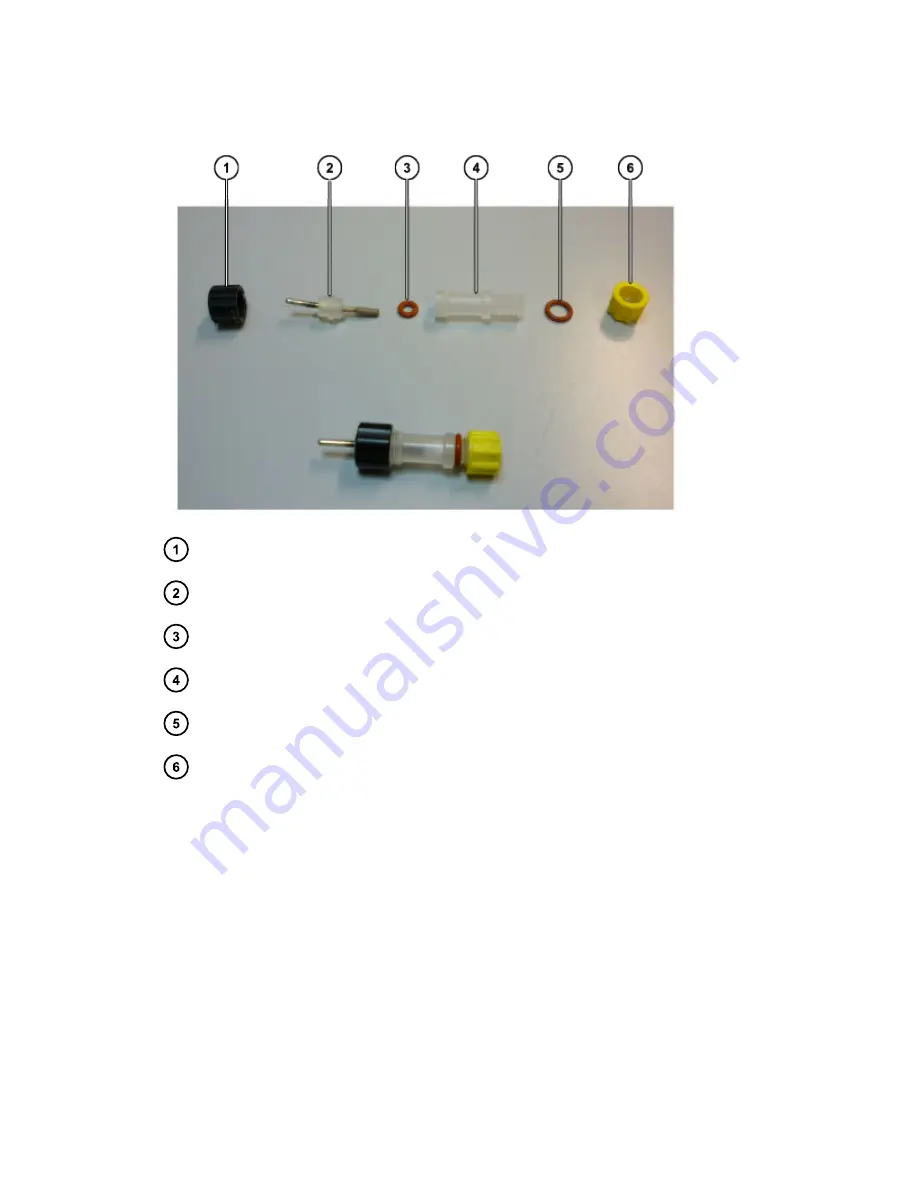
Figure 14–9: Salt bridge Ag/AgCl reference electrode, assembled (bottom) and
disassembled (top)

sb REF swivel (700001956)

sb REF Ag/AgCl electrode (700002254)

sb REF silicon O-ring small (700002175

a

)

sb REF body (700001957)

sb REF silicon O-ring large (700002175

a

)

sb REF sealing cap

a. 700002175 contains one small and one large O-ring.

The yellow cap prevents drying out of the cotton frit that is mounted in the tip of the body.

14.4.7 Salt bridge Ag/AgCl reference electrode check

For proper functioning, the salt bridge reference electrode should have crystals inside the body
(to ensure a saturated solution), no air bubbles inside the body, and a permeable wet cotton frit in
the body tip.

Visually inspect for the presence of crystals inside the REF

After prolonged use the salt bridge in the REF body will no longer be saturated, which usually
leads to poor reproducibility in electrochemical detection. If the salt bridge is not saturated and
the KCl concentration decreases:

December 16, 2021, 715007395 Ver. 00

Page 116

Содержание 3465

Страница 1: ...Waters 3465 Electrochemical Detector Overview and Maintenance Guide 715007395 Version 00 Copyright Waters Corporation 2021 All rights reserved...

Страница 2: ...l Waters Corporation be liable for incidental or consequential damages in connection with or arising from its use For the most recent revision of this document consult the Waters website www waters co...

Страница 3: ...or conventional mail Contact method Information www waters com The Waters website includes contact information for Waters locations worldwide iRequest Request technical support for your Waters instrum...

Страница 4: ...formed by the manufacturer or a company authorized by the manufacturer and suitable training on the system and chromatography software Knowledge and experience in the safe handling of toxic and corros...

Страница 5: ...oratory use EMC requirements EMC emissions Do not use the equipment in close proximity to sources of strong electromagnetic radiation for example unshielded intentional RF sources The radiation can in...

Страница 6: ...all applicable United States and Canadian safety requirements Environmentally friendly use period China RoHS indicates the number of years from the date of manufacture until the product or components...

Страница 7: ...control the hazard Electrical power safety notice Do not position the device so that it is difficult to disconnect the power cord Equipment misuse notice If equipment is used in a manner not specified...

Страница 8: ...lly dangerous voltages Disconnect the device from all power sources before disassembly Untrained personnel should not open the instrument This may only be done by authorized service engineers Replace...

Страница 9: ...a flat smooth surface Do not block the ventilation holes located at the bottom and lower rear panel of the detector Blocking these holes may impair the cooling capability of the power supply Solvents...

Страница 10: ...nd ensure adequate ventilation and air exchange in the laboratory Waste disposal Perform periodic leak checks on LC tubing and connections Do not close or block the drain in the oven compartment Do no...

Страница 11: ...nd If sample trays are the same or very similar vary the location of the QC samples in the trays Ensure that QC sample results fall within an acceptable range and evaluate precision from day to day an...

Страница 12: ...Legal manufacturer v Safety considerations v Applicable symbols v Safety hazard symbol notice vii Electrical power safety notice vii Equipment misuse notice vii Considerations specific to the device...

Страница 13: ...iodic check of the oven temperature 39 3 1 3 Flow cell 39 3 1 4 Cleaning 40 3 1 5 Replacement of fuses 40 3 2 Shutting down the system 40 4 Detector controller 42 4 1 Introduction 42 4 2 Overview of 3...

Страница 14: ...2 Frequency 64 7 2 1 Frequency of signal and noise 65 7 2 2 Low pass noise filters 67 7 2 3 Amplitude response plot 68 7 3 Applying ADF in chromatography 69 8 Pulsed amperometric detection PAD 72 8 1...

Страница 15: ...nal weight and power requirements 81 10 2 3465 General 82 10 3 3465 DC Mode 82 10 4 3465 PULSE mode 83 10 5 3465 PULSE mode 2 83 10 6 3465 SCAN mode 83 11 Rear panel I O 85 11 1 USB B connector 85 11...

Страница 16: ...odes 104 14 1 5 Reference electrode 105 14 2 General precautions 109 14 3 Installation 110 14 3 1 Connecting a FlexCell to an LC system 111 14 4 Maintenance 112 14 4 1 Disassembly of the flow cell 112...

Страница 17: ...5 3 3 Installation in LC system 136 15 3 4 Installing the SenCell 136 15 4 Maintenance 140 15 4 1 Assembling disassembling the cell 140 15 4 2 HyREF 142 15 4 3 ISAAC 142 15 4 4 Ag AgCl salt bridge 144...

Страница 18: ...175 16 4 3 Ag AgCl salt bridge 176 16 4 4 Working electrode 179 A Safety advisories 181 A 1 Warning symbols 181 A 1 1 Specific warnings 182 A 2 Notices 183 A 3 Bottles Prohibited symbol 184 A 4 Requi...

Страница 19: ...highly stable Faraday shielded oven compartment accommodating column and flow cell The flow cell provides an unsurpassed S N ratio for extremely sensitive electrochemical analyses The 3465 Detector h...

Страница 20: ...trument description Figure 1 1 3465 Detector Front side Instrument housing LC tubing inlet outlet Instrument door panel 4 x 40 Ch LCD display Function keys Enter key December 16 2021 715007395 Ver 00...

Страница 21: ...gure 1 2 3465 Detector Back side Instrument rear panel Digital I O connector 25 p sub D fem Analog data 9 pin sub D fem Valve connector 9 pin sub D male LAN connector RJ45 jack USB connector USB B Typ...

Страница 22: ...ing stud Mains switch inlet Ventilation holes Fuse compartment Figure 1 3 3465 Detector Oven compartment Door panel rear Type label Door sensor Door lock Drain Mounting hole column clamp December 16 2...

Страница 23: ...Bottom fan heater exhaust Mounting hole cell clamp Flow cell clamp Column clamp Mounting plate Top fan heater intake Cell connector 9 pin sub D Cell cabinet December 16 2021 715007395 Ver 00 Page 23...

Страница 24: ...e installation site must comply with applicable local laws and regulations with regard to electrical and mechanical installations building safety the use and disposal of potentially hazardous material...

Страница 25: ...e only in an industrial or commercial environment EN55011 group 1 class B ISM equipment It is suitable for the following categories installation category II pollution degree 2 and equipment class I Ta...

Страница 26: ...ptible Power Supply UPS The main supply must include a correctly installed protective earth conductor Notice To protect against power transients voltage spikes and power surges it is recommended that...

Страница 27: ...arrives Immediately inform the transport company of any damage otherwise it may not accept responsibility Keep the transport box it is designed for optimum protection during transport and may be neede...

Страница 28: ...tor indoors only Place the detector upright on its instrument feet on a stable flat and smooth surface Do not place the instrument in an area subject to excessive dust or shocks Do not place it near a...

Страница 29: ...ress 192 168 0 65 with subnet mask 255 255 255 0 Gateway and DNS are not filled in The instrument is delivered with a special crossover LAN UTP cable Waters PN 700013076 which is part of the 3465 Dete...

Страница 30: ...r Set the detector temperature to 35 C if an Operational Qualification OQ will be executed or set it to the temperature at which your ECD application is running Allow the instrument to stabilize for a...

Страница 31: ...software by submitting an iRequest Double click on the setup exe file to start the installation wizard Follow the instructions of the installation wizard for successful installation of the software In...

Страница 32: ...ically for use in Ultra High Performance Liquid Chromatography and capable of delivering flow rates in the range of 1 L min to 2 mL min The manufacturer accepts no liability for damage direct or indir...

Страница 33: ...age to the port of the valve column or other part Part of the tubing may end up in the connection port internals Internals of the port may be damaged Figure 2 5 Length is too long Ferrule does not sea...

Страница 34: ...ctrochemically active and is not recommended In that case only a passivation step with 30 H3PO4 is recommended Electrolytes ensure contact between the three electrodes in an electrochemical flow cell...

Страница 35: ...the dampener and the injector in load and inject positions and then routed to waste Notice Ensure that all parts that are not acid resistant such as nylon inlet filters column and flow cell are not c...

Страница 36: ...ve 50 C Notice Do not use the flow cells at temperatures above 50 C higher temperatures might lead to damage of the cell 7 See the Figure 2 8 SenCell mounted at an angle of approximately 45 in the det...

Страница 37: ...stainless steel Bottom right SenCell with salt bridge reference electrode 8 Before switching ON the flow cell ensure that the mobile phase contains sufficient electrolyte buffer ions A stable baseline...

Страница 38: ...without jumps or spikes 11 Connect the 3465 Detector to the PC control software Empower 3 Your system is now ready for use The 3465 Detector has been developed for continuous operation For maximum st...

Страница 39: ...rform regular checks to verify if the actual oven temperature is in accordance with the set temperature of the 3465 Detector Warning If the actual temperature exceeds 70 C switch off the detector imme...

Страница 40: ...cord from the receptacle on the back of the unit For continued protection against fire replace fuses with those of the same type and rating only As a general practice even when only one out of two fus...

Страница 41: ...of a salt bridge REF cap it and store it separately to prevent drying out Alternatively put the sb REF in a 10 mL vial under a KCl solution and close the vial with a cap 8 Switch off the detector and...

Страница 42: ...is given together with the item s nature and the screen or screens that appear The nature of an item can be Control parameters with a cursor box can be attained via cursor buttons and changed by the v...

Страница 43: ...3465 Detector keyboard The cursor is on Range which allows changes using the value buttons and The Enter button is used only to confirm changes in potential Ec and range December 16 2021 715007395 Ver...

Страница 44: ...4 2 Overview of 3465 Detector screens Figure 4 2 DC mode Figure 4 3 Pulse mode December 16 2021 715007395 Ver 00 Page 44...

Страница 45: ...Figure 4 4 Scan mode Figure 4 5 CONFIG menu December 16 2021 715007395 Ver 00 Page 45...

Страница 46: ...e actual left hand value and the preset oven temperature right hand value S AZERO PULSE STAT DC STAT RUN PULSE STAT SCAN STAT Sets the output voltage to 0 V or to the offset voltage Control Comp off c...

Страница 47: ...e of the cycle half full and continuous Half means that the cell potential runs from E1 to E2 and stops at E2 Full means that the cell potential runs from E1 to E2 back to E1 and then stops Cont means...

Страница 48: ...to zero or offset F ID1 master CONFIG Sets sensor board 1 as master When this setting is set to yes all parameter settings from sensor board 1 are automatically copied transferred to all other sensor...

Страница 49: ...ogrammable input Can be configured so that the signal of cell 1 2 or 3 is zeroed when active or ALL cells C P21 START IO Programmable input Can be configured so that the data acquisition on sensor boa...

Страница 50: ...s the duration of the sampling time in pulse mode The time can be set between 20 ms and t1 60ms in 20 ms increments C Tsensor SYSTEM Displays active temperature sensor S Valve CONFIG User confirmation...

Страница 51: ...h a three electrode configuration Fig 5 1 The working potential is set between the working electrode WE and the auxiliary electrode AUX The AUX is kept at a precisely defined reference electrode REF p...

Страница 52: ...l current is amplified by the current potential I E converter Figure 5 2 3465 Detector signal processing from electrochemical flow cell to output The signal from the I E converter can be compensated w...

Страница 53: ...Figure 5 3 Typical configuration for serial mode detection Cell 1 is a FlexCell cell 2 is a SenCell for detection Empower channel 1 and 2 use the same time base as system 1 Degasser Pump 1 Inject 1 C...

Страница 54: ...or STAT screen in DC PULSE and SCAN modes A number of ranges can be selected the maximum current that can be compensated for using auto zero and offset differs among ranges The high sensitivity range...

Страница 55: ...nA 2 5 A In the PULSE and SCAN modes current is much higher than in DC mode Therefore it is not possible to select pA ranges Table 5 2 Table 3 PAD ranges and maximum compensation Range Max comp Range...

Страница 56: ...gnal to noise ratio of the analysis The next chapter explains the filter setting including detailed background information about filtering 5 6 1 DC mode In the following tables the available filter se...

Страница 57: ...steps in a pulse t1 t2 t3 t4 t5 The typical pulse duration is between 0 5 and 2 s data rate between 2 and 0 5 Hz Filter settings in pulse mode are selectable between 0 5 and 0 001 Hz and OFF 5 6 3 Pu...

Страница 58: ...vior An Autozero offset or change of measurement range will trigger an internal calculation procedure in the detector based on the actual cell current This is an iterative process the cell current is...

Страница 59: ...gs DC mode can be used for detection using relatively inert working electrode WE materials such as glassy carbon GC or boron doped diamond Suitable analytes in this case are typically aromatic compoun...

Страница 60: ...l is measured red part This mode is particularly useful for certain applications where the working electrode is rapidly fouled due to adsorption of reactant or reaction products or and when using meta...

Страница 61: ...steps can be defined in pulse mode The sampling interval period at which the current is measured is applied at the end of E1 More detailed information about pulsed amperometric detection is available...

Страница 62: ...in manual operation using keyboard display The new pulse mode can only be used through software control Empower When disconnecting the device from the CDS it automatically switches back to the standar...

Страница 63: ...it is not a measurement mode used in HPLC ECD analysis itself It is available only in stand alone operation Scan mode is not available in any CDS See Optimization of the working potential Page 76 for...

Страница 64: ...the number of completed alterations per unit of time It has two dimensions count and time Frequency is usually expressed in Hz which is counts per second The counts themselves can run in a regular ev...

Страница 65: ...etermine this frequency is the same The duration of the full peak is measured and expressed in Hz Figure 7 3 Frequency tells how often something happens 1 peak in about 0 25 min 15 s f 1 15 0 07 Hz Th...

Страница 66: ...ponds to 10 100 s peak width Figure 7 5 Typical chromatogram with peak widths between 10 and 100 s Noise in chromatography can come from various sources Pump pulsations are typically shown as a very r...

Страница 67: ...ed A passive RC filter consists of resistors and capacitors An active higher order filter can be considered as a series of these RC filters In a fourth order filter the signal coming from the first fi...

Страница 68: ...etween 0 Hz and 1 Hz and all higher frequencies are noise An ideal filter is shown in Figure 7 7 Amplitude response plot of an ideal low pass filter with a cutoff frequency of 1 Hz Page 68 where signa...

Страница 69: ...of a digital filter improves with more input data points but greater processor capacity is required for the large number of calculations 7 3 Applying ADF in chromatography If noise frequencies in LC...

Страница 70: ...low stronger filter settings simply because of the lower frequency of such peaks A recommended filter setting to start further optimization is given as Filter setting 1 2 peak width So at a 10 s peak...

Страница 71: ...t up to a factor 100 compared with an unfiltered signal may be obtained As high frequency noise is suppressed remaining noise components will be in the same frequency range as chromatographic peaks Be...

Страница 72: ...series of potential steps is applied in a cyclic manner The signal is sampled during a fraction of the total pulse cycle During the sampling time ts the signal is collected and the value is sent to d...

Страница 73: ...mands on the HPLC system and flow cells After prolonged use of a flow cell with a gold working electrode WE in pulse mode the gold oxide that is generated at the WE precipitates on the auxiliary elect...

Страница 74: ...d detection frequency It might seem that the number of variables five potential steps and six time settings would lead to a time consuming optimization procedure In practice pulse mode is more straigh...

Страница 75: ...1 7 References 1 D C Johnson D Dobberpuhl R Roberts and P Vandenberg Review Pulsed amperometric detection of carbohydrates amines and sulphur species in ion chromatography the current state of resear...

Страница 76: ...tage runs between two preset potential values E1 and E2 and scan speed in mV s and the current is measured 9 2 Electrochemical reactions In electrochemical detection ECD a reaction of the analyte at a...

Страница 77: ...e at a glassy carbon working electrode A and the current of the baseline B At E1 the electrochemical signal becomes diffusion limited 9 3 2 Scanning voltammogram An alternative for the chromatographic...

Страница 78: ...iffusion only Therefore the current at and beyond this potential is called the diffusion limited current Figure 9 4 Scanning voltammetry of 1 0 mol L norepinephrine A at a glassy carbon working electr...

Страница 79: ...tive For norepinephrine the I E curve shifts to a lower potential at higher pH When the working potential is high E2 and the signal is diffusion limited an increase in pH results only in a small incre...

Страница 80: ...y active In such cases derivatization of the compound may be an option 4 If a peak is measured the working potential is decreased by 50 or 100 mV and steps 2 through 4 are repeated until the lowest po...

Страница 81: ...stall upright on flat and smooth surface keep space under the detector free Power requirements 100 240 VAC 50 60 Hz 260 VA auto sensing Main fuse 2 5 AT 250 V 5 x 20 mm IEC 60127 2 For safety reasons...

Страница 82: ...anel connectors 1x IEC inlet Main 1x USB B 1x RJ45 LAN 1x 9 pin sub D Male Valve 1x 9 pin sub D Female Analog output 1x 25 pin sub D Female Digital I O Analog output DAC 1 to 1 V full scale via 16 bit...

Страница 83: ...ms 2000 ms t2 t3 t4 t5 0 2000 ms in 10 ms increments Sampling times ts 20 ms t1 60 ms 10 5 3465 PULSE mode 2 Range 10 nA 200 A in 1 2 5 increments Filter ADF 0 5 0 01 Hz in 1 2 5 increments OFF for u...

Страница 84: ...Potential Ec 2 50 V to 2 50 V in 10 mV increments Data rate 1 Hz Scan rate 1 100 mV s in 1 2 5 increments Cycle Half Full Continuous December 16 2021 715007395 Ver 00 Page 84...

Страница 85: ...USB type B connector for serial instrument control over USB for service use only Based on USB to serial UART interface using the FT232R chip from FTDI Future Technology Devices International Ltd FT23...

Страница 86: ...e detector has one 25 pin digital I O connector the XE digital I O connector which enables control of or by external equipment The I O connector contains 18 TTL contacts 5 outputs and 13 inputs 3 3 V...

Страница 87: ...cell current goes out of range during the recording of an analyte peak it can in most cases be easily recognized by a flat peak top and a very abrupt transition to the flat top at the edges By defaul...

Страница 88: ...are 1 2 3 4 5 and all If all is selected all cells present in the 3465 Detector are switched on or off when the corresponding input is triggered 11 3 6 Autozero The 3465 Detector has three TTL inputs...

Страница 89: ...partment This grounding stud is connected to the central grounding point of the instrument and can be used for shielding purposes for example to shield the flow cell outlet from external electrical in...

Страница 90: ...r rear panel grounding stud Right example of shielding the flow cell by grounding the solvent outlet tubing Note Use the chassis grounding stud for shielding only not for safety grounding December 16...

Страница 91: ...ns The error messages appear in the instrument s LCD display Table 12 1 Error messages Error Message 11 Checksum error 12 Temperature sensor 1 error 13 Disconnect flow cell x 14 Control board SDRAM er...

Страница 92: ...out again If not the autozero function cannot compensate the background cell current Advice Use a less sensitive range in the SETUP menu 02 PAD overload The charging current in pulse mode is out of ra...

Страница 93: ...al is stable We recommend programming the autozero at the beginning of the run during the hold up time before the unretained solvent peak elutes or at the end of the run 12 2 Analytical troubleshootin...

Страница 94: ...olerance of the resistor 1 The capacitor functions as a noise generator and in fact resembles the capacitance of a well functioning VT 03 flow cell in an ideal UPLC setup The noise generated via the d...

Страница 95: ...ell the noise should be better than 2 pA Detector settings in the NOISE screen are the same as in the external dummy cell test with the exception of the oven temperature Temperature is switched off Fi...

Страница 96: ...example a drop of more than 50 it is an indication that the problem is not flow cell related but originates from other parts of the LC system The most obvious reasons for a high background current are...

Страница 97: ...unning trouble free before and that no changes were made to the system A number of causes and possible solutions for analytical problems are listed here Contact your local representative if you need f...

Страница 98: ...Air bubble in REF or in cell Remove air bubble continuously degas the mobile phase Slow temperature fluctuations Isolate detector cell set oven temperature Fouled WE Clean WE Leaking REF or cell Tight...

Страница 99: ...ts Adjust cell bolts check pump pressure Air bubbles in cell or REF Maintenance REF Temperature oscillations Set oven temperature Contaminated buffer high Icell Replace buffer do not recycle the buffe...

Страница 100: ...ed 3 m 700013077 USB cable A B 3 m 700013074 I O conn board 700013075 I O cable 25M 25M 1 8 m 700013073 Output cable D9 male open 2 m 700013078a Cell cable a For Dual Cell ECD the quantity of 70000194...

Страница 101: ...Figure 13 1 Part 700013073 3465 Detector SCC output cable D9 December 16 2021 715007395 Ver 00 Page 101...

Страница 102: ...y exchangeable offering maximum flexibility for running various applications Also in applications where the working electrode material is electrochemically consumed the option for an easy exchange is...

Страница 103: ...cell with a three electrode configuration Essentially for the oxidation or reduction reaction it would be sufficient to use only two electrodes However the three electrode configuration has several a...

Страница 104: ...king electrodes 14 1 4 1 Various WE materials The surface of the working electrode is where the electrochemical reaction takes place This puts specific demands on the working electrode material The WE...

Страница 105: ...ted on a Si wafer The electrode is anodized and is capable of detecting oxidized components at 1 5 2 V which would otherwise require a reductive step before detection under oxidative conditions Other...

Страница 106: ...xed value Figure 14 3 Difference in reference potential when comparing HyREF with saltbridge Ag AgCl REF at different mobile phase pH 14 1 5 2 Salt bridge Ag or AgCl The salt bridge Ag AgCl reference...

Страница 107: ...representation of the salt bridge Ag AgCl reference electrode Ag AgCl KCl saturated KCl crystals Cotton wool Three aspects determine the proper function of an Ag AgCl reference electrode December 16...

Страница 108: ...be prepared with the same concentration of chloride ions typically 2 mM to get reproducible results Important It is important to add a fixed concentration of chloride ions to the mobile phase when us...

Страница 109: ...he restrictions using ISAAC is mentioned below A high working potential 1 2 V vs Ag AgCl in 2 mmol L KCl will oxidize Cl which then contributes to background current and noise In ion chromatography th...

Страница 110: ...oth fluid connections can be used as either inlet or outlet Notice Never switch on the flow cell if The black red and blue cell cable is not correctly connected The cell is only partly or not at all f...

Страница 111: ...cut 0 5 mm ID PEEK tubing to the flow cell outlet 5 For a salt bridge reference electrode first make sure it is ready for use Notice When using a salt bridge reference electrode inspect it visually b...

Страница 112: ...he cell Important Before disassembling the flow cell read the General Precautions 14 4 1 Disassembly of the flow cell To disassemble the flow cell 1 Switch the flow cell off set the flow rate to zero...

Страница 113: ...ted on the electrode shaft with electrode retaining ring Held in place by a silicon electrode holder Figure 14 8 Exploded view of FlexCell Auxiliary electrode inlet block Retaining ring Working electr...

Страница 114: ...lied to non BDD electrodes BDD electrodes must be replaced in such cases 14 4 3 Polishing a working electrode To polish a working electrode 1 Shake the container with diamond slurry thoroughly before...

Страница 115: ...d instructions are provided with the kit 14 4 5 HyREF and ISAAC reference electrodes The HyREF and ISAAC reference electrodes are in principle maintenance free When not in use they should be stored dr...

Страница 116: ...of the body 14 4 7 Salt bridge Ag AgCl reference electrode check For proper functioning the salt bridge reference electrode should have crystals inside the body to ensure a saturated solution no air...

Страница 117: ...lling air bubble or lack of crystals inside the body the following materials are necessary for salt bridge filled with KCl Small plastic pipette Potassium chloride 30 mL of KCl solution saturated with...

Страница 118: ...the cotton wool frit To remove cotton wool frit 1 Unscrew the black swivel from the body Figure 14 9 Salt bridge Ag AgCl reference electrode assembled bottom and disassembled top Page 116 2 Remove th...

Страница 119: ...w cell increases the noise level considerably To assemble the flow cell 1 Take the working electrode disk and press it in its silicone holder Try not to touch the active middle surface 2 Clean fingerp...

Страница 120: ...LC system we recommend that you disassemble the cell and clean and dry all surfaces Warning Before flushing the LC system and uncoupling the cell from the detector turn off the cell 14 5 Specificatio...

Страница 121: ...1 16 inch o d PEEK tubing with 10 32 PTCFE fingertight connectors Electric connections Cell cable for use with 3465 Detector 14 6 Parts list Table 14 4 Spare parts for the FlexCell Part number Descrip...

Страница 122: ...disk for WE 700001955 10 mL diamond slurry 1 m 700013150 Flattening polishing kit for metal WE Parts for reference electrode maintenance 700013253 30 mL KCl solution saturated with AgCl 700013145 Sal...

Страница 123: ...AAC Figure 15 1 Assembled SenCell electrochemical flow cell with ISAAC inlet block green The upper part the inlet block is separated from the working electrode block Right SenCell WE block The SenCell...

Страница 124: ...he electrodes resulting in highly unstable working conditions If the working potential would be applied only over the REF versus the WE without AUX the working potential would be very well defined How...

Страница 125: ...uents or WE material that occurs when the potential exceeds the limits as given in the preceding table At high positive working potentials the water in the mobile phase electrolyzes and results in a s...

Страница 126: ...ndard deviation of the noise Where sigma noise is 0 2 x peak to peak noise and cA is the concentration of analyte injected The Example S N ratio for norepinephrine Page 127 image shows a typical S N r...

Страница 127: ...50 m spacer is 80 nL and 160 nL respectively The signal increases with thinner spacers while the noise remains more or less constant which can lead to improvement in detection sensitivity signal to n...

Страница 128: ...acing setting of 100 m and 12 m respectively The preceding chromatogram images show an example to demonstrate the effect of cell working volume on signal In the following image on Normalized peak heig...

Страница 129: ...aracterized by an increased noise level and a rise in system back pressure Warning Applying low working volume settings should be done with great care because it may cause excessive pressure buildup o...

Страница 130: ...ht balance between signal height and noise level for your SenCell under your specific LC EC conditions You can achieve optimization by decreasing the cell spacing in small steps and evaluating the bas...

Страница 131: ...0 mol L Cl solution for the following half reaction is defined as E0 The potential of the REF is dependent on the chloride concentration as described by the following equation where R is the gas const...

Страница 132: ...For example the ISAAC is not recommended at a high working potential 1 2 V vs Ag AgCl in 2 mmol L KCl because Cl is oxidized and contributes to the background current In ion chromatography the additio...

Страница 133: ...th the other electrodes in the flow cell is made through a salt bridge consisting of a wetted cotton wool frit which is electrically conducting and slows down leakage of KCl This REF for the SenCell i...

Страница 134: ...ing a shift of more than 200 mV at pH 3 1 for example catecholamines no shift appears at pH 12 for example PAD of carbohydrates Therefore it is best to first construct a hydrodynamic or scanning volta...

Страница 135: ...bore LC columns 2 mm 4 6 mm ID and flow rates 200 L min When using micro bore LC columns position 1 25 10 m is recommended for working volume 15 3 2 Adjusting the SenCell working volume Figure 15 11...

Страница 136: ...als Notice If an ISAAC reference electrode is used ensure that the mobile phase contains at least 2 mmol L chloride KCl or NaCl ions 4 Passage of air bubbles through the flow cell will lead to unaccep...

Страница 137: ...tting is completely filled with mobile phase mount the REF while slowly releasing the outlet Make sure not to entrap an air bubble 6 Position the flow cell in its clamp in the controller with the REF...

Страница 138: ...o prevent entrapped air bubbles Cell inlet tubing connection from column to cell WE contact red AUX contact blue REF contact black Top Left SenCell with ISAAC reference electrode green inlet block Top...

Страница 139: ...installed Make the electrical connections as depicted in the following figure Figure 15 14 Installation of flow cell WORK AUX and REF are connected using the red blue and black cell cables Note LC ou...

Страница 140: ...1 Assembling disassembling the cell Figure 15 15 Exploded view of SenCell WE block O ring Inlet block Inlet block O ring Closing ring The arrows indicate how to assemble the cell December 16 2021 7150...

Страница 141: ...ockwise by hand 4 Remove the inlet block 5 Remove the silicon O ring orange brown colored from the WE block Note The cell is now fully disassembled 15 4 1 2 Assembling the cell To assemble the cell 1...

Страница 142: ...SAAC solution After coating the ISAAC electrode surface should show a brownish reddish matt finish AgCl layer If not used for a longer period of time disassemble the flow cell Clean the flow cell incl...

Страница 143: ...1 After polishing coat the ISAAC REF with the factory supplied ISAAC solution 700001949 2 Apply the coating for 20 minutes 3 Flush away the solution with distilled water The ISAAC electrode surface s...

Страница 144: ...ger be saturated which usually leads to poor reproducibility in electrochemical detection The potential of the REF is determined by the chloride concentration If the salt bridge is not saturated and t...

Страница 145: ...Salt bridge body REF cap for storage and shipment 7 Remove the remaining KCl from the salt bridge 8 Clean all parts with demi water 9 The frit in the salt bridge ensures electrical contact with the b...

Страница 146: ...bble 8 Tighten the fitting such that a small droplet appears at the end of the salt bridge but do not over tighten it 9 Flush the complete mounted REF with demi water and dry it with a tissue but keep...

Страница 147: ...jump between 1 and 1 V for 10 minutes Settings t1 1000 ms t2 1000 ms t3 0 ms E1 1V and E2 1V 2 Wiping the electrode surface with a tissue wetted with ethanol or acetone 3 Polishing the electrode surf...

Страница 148: ...its plastic bag 15 5 Specifications Table 15 5 Specifications for SenCell Specifications Description Cell type Three electrode wall jet flow cell Cell working volume based on 2 mm WE 0 300 nL steples...

Страница 149: ...ring 700013052 SenCell 2 mm GC sb 700013070 SenCell 2 mm GC ISAAC 700013055 SenCell 2 mm GC HyREF 700013130 SenCell WE block 2 mm GC WE 700013133 SenCell inlet block sb REF w o sb REF 700013134 SenCe...

Страница 150: ...ode In combination with the spacer set 25 50 and 120 m a variety of detection volumes down to 5 nL can be attained As a standard the salt bridge Ag AgCl reference electrode is recommended For special...

Страница 151: ...is separated from the working electrode block by means of a gasket spacer not shown The VT 03 electrochemical flow cell was developed for ultra trace analysis in standard microbore and capillary LC E...

Страница 152: ...three electrode configuration Figure 16 2 Schematic of an electrochemical cell with a three electrode configuration Page 153 The working potential is set between the working electrode WE and the auxil...

Страница 153: ...change due to polarization effects at the electrodes resulting in highly unstable working conditions If the working potential were applied only over the REF versus the WE without AUX the working poten...

Страница 154: ...0 80 1 30 Catecholamines Gold 1 25 0 75 0 35 1 10 Carbohydrates Platinum 0 90 0 65 0 20 1 30 Alcohols glycols Silver 1 20 0 10 0 55 0 40 Halides cyanide Copper 0 60 Amino acids carbohydrates Another c...

Страница 155: ...a noise is 0 2 x peak to peak noise and cA is the concentration of analyte injected Figure 16 3 Typical S N ratio for norepinephrine measured with a VT 03 glassy carbon flow cell peak height 80 nA pea...

Страница 156: ...f the WE is an important factor in LC EC it affects both the signal and the noise For the VT 03 flow cell several glassy carbon WE diameters are available 0 7 2 and 3 mm In a standard LC system the si...

Страница 157: ...16 1 6 Spacer thickness The thickness of the gasket affects the linear flow velocity in the cell With a thinner spacer the cell volume decreases Table 16 4 Flow cell volume Page 159 resulting in highe...

Страница 158: ...pinephrine The signal and noise for 1 0 mol L norepinephrine measured at variable spacer thickness given in m See Table 16 2 LC EC conditions for analysis of norepinephrine Page 155 for other conditio...

Страница 159: ...0 020 0 011 0 005 50 0 35 0 29 0 25 0 16 0 14 0 039 0 022 0 010 120 0 85 0 71 0 61 0 38 0 34 0 094 0 053 0 024 16 2 Reference electrodes The VT 03 flow cell is available with an ISAAC in situ Ag AgCl...

Страница 160: ...KCl Ag AgCl reference electrode and the ISAAC is 189 mV If an application is running at 800 mV vs Ag AgCl with saturated KCl the potential setting using the ISAAC should be 611 mV vs Ag AgCl in 2 mmol...

Страница 161: ...For example the ISAAC is not recommended at a high working potential 1 2 V vs Ag AgCl in 2 mmol L KCl because Cl is oxidized and contributes to the background current In ion chromatography the additio...

Страница 162: ...Figure 16 7 Schematic representation of the Ag AgCl reference electrode Ag AgCl coating KCl saturated KCl crystals Cotton wool December 16 2021 715007395 Ver 00 Page 162...

Страница 163: ...Consequently refilling the REF with saturated KCl is not required Due to the absence of a salt bridge and its inertness the HyREF is an excellent alternative to the Ag AgCl REF especially in high modi...

Страница 164: ...using the red blue and black cell cables Note LC out should be on top to prevent entrapment of bubbles Warning The ISAAC reference electrode requires 2 mmol L chloride ions KCl or NaCL in the mobile...

Страница 165: ...ell is only partly or not at all filled with buffer electrolyte The outside of the flow cell is wet particularly the part between the auxiliary and working electrode connection because substantial dam...

Страница 166: ...the cap 2 Tighten the black swivel of the REF A small droplet should appear at the cotton wool frit Do not remove this droplet because it ensures proper contact of the REF with the mobile phase 3 Turn...

Страница 167: ...cable as illustrated in Figure 16 9 Installation of flow cell Page 166 Maximum detection stability is attained when not only the flow cell but also the HPLC column is incorporated in the controller T...

Страница 168: ...S N ratio and eventually the cell itself Also be aware that the black marks on both blocks should be in line 16 3 3 1 Assembling the micro flow cell The VT 03 micro flow cell has a 0 7 mm WE and is eq...

Страница 169: ...3 mm GC using a similar procedure Note Mounting the cell in another manner may lead to damage of the spacer and flow cell blocks For cells without a metal centering ring skip the sections in the proc...

Страница 170: ...ers The spacer should lay flat on the WE surface with the bolts centered in the spacer bolt holes Figure 16 13 Placement of 25 m spacer on the WE block 3 Place the inlet block on top of the WE block a...

Страница 171: ...should now be aligned in vertical position Figure 16 14 Positioning the inlet block on top of the WE block Figure 16 15 Inlet block positioned on top of WE electrode Note that the black positioning m...

Страница 172: ...columns 1 mm ID fused silica columns as a standard Important Use proper eye and skin protection when working with solvents Note If the capillary connection is already installed properly continue with...

Страница 173: ...ry to the pump bypassing the column and switch on the pump to confirm that the capillary is open Liquid droplets must come out Otherwise install a new piece of 100 m FS tubing Note that both ends of t...

Страница 174: ...A the standard installation with capillary connector 2 is shown This is suitable for fused silica columns On the right B installation with a ferrule and sleeve connected to the column is shown 11 Con...

Страница 175: ...enance usually not more than once every three months In practice this means that when the flow cell is opened to service the working electrode the reference electrode should be serviced as well Figure...

Страница 176: ...r close to the salt bridge will lead to instability of the three electrode configuration Because of their extreme compressibility changes in conductivity and the ionic equilibrium of the REF occur Thi...

Страница 177: ...sconnect the cell from the controller 4 Remove the REF from the inlet block 5 Disassemble the REF by unscrewing the black fitting 6 Inspect the O ring for wear and especially the cotton wool frit Repl...

Страница 178: ...mm 0 039 inch to push out the frit from the outside Be careful not to damage the frit constriction first arrow Figure 16 22 Pushing out the cotton wool frit 2 Clean the salt bridge thoroughly with ta...

Страница 179: ...ectrode lacks its mirror like finish and cannot be restored by wiping the electrode surface with a tissue wetted with ethanol or acetone 16 4 4 1 Decreased flow cell performance Warning Use proper eye...

Страница 180: ...entle pressure 4 Clean the electrode with an ethanol wetted tissue and inspect the surface visually Repeat the procedure if necessary until the shining metal REF surface appears 5 Reassemble the detec...

Страница 181: ...ry or property damage resulting from the failure of individuals to comply with any safety precaution when installing repairing or operating any of its instruments or devices The following symbols warn...

Страница 182: ...d devices fitted with nonmetallic tubing Warning To avoid injury from bursting nonmetallic tubing heed these precautions when working in the vicinity of such tubing when it is pressurized Wear eye pro...

Страница 183: ...cal hazard warning This warning applies to Waters instruments and devices that can process biohazards corrosive materials or toxic materials Warning To avoid personal contamination with biologically h...

Страница 184: ...pply to all Waters instruments and devices When operating this device follow standard quality control procedures and the equipment guidelines in this section Warning Changes or modifications to this u...

Страница 185: ...ide and dimethyl sulfoxide cause nonmetallic tubing to swell which greatly reduces the rupture pressure of the tubing Avertissement Manipulez les tubes en polym re sous pression avec precaution Portez...

Страница 186: ...zzare tubi eccessivamente logorati o piegati Non utilizzare tubi non metallici con tetraidrofurano THF o acido solforico o nitrico concentrati Tenere presente che il cloruro di metilene e il dimetilso...

Страница 187: ...etrahydrofuran THF Methylene chloride Dimethyl sulfoxide THF This warning applies to Waters instruments fitted with nonmetallic tubing or operated with flammable solvents December 16 2021 715007395 Ve...

Страница 188: ...chiatura secondo modalit non previste dal produttore pu compromettere la protezione offerta dall apparecchiatura Advertencia el usuario deber saber que si el equipo se utiliza de forma distinta a la e...

Страница 189: ...does not appear on the instrument or device Warning To protect against fire replace fuses with those of the type and rating indicated in the Replacing fuses section of the Maintenance Procedures chap...

Страница 190: ...ls Symbol Description Electrical power on Electrical power off Standby Direct current Alternating current Alternating current three phase Safety ground Frame or chassis terminal connection Fuse Functi...

Страница 191: ...n appear on labels affixed to the packaging in which instruments devices and component parts are shipped Symbol Description Keep upright Keep dry Fragile Use no hooks Upper limit of temperature Lower...

Отзывы: