P
age
28
4.
4
Ba
ffl
e
P
o
si
ti
o
n
in
g
21,
26
&
33
Mo
d
el
s
T
he
prima
ry
heat
ex
ch
anger
baf
fle
s
con
sist
of
one
he
avy
baf
fle
st
ack
(5
mm
thi
ck)
at
t
he
bot
to
m,
3
lig
ht
er
ba
ff
le
st
acks
(3
m
m
thi
ck)
in
t
he
mi
ddl
e
and
1
baf
fle
plat
e
(3
mm
th
ic
k)
at
t
he
to
p.
Up
on
in
st
alla
tio
n
or
af
ter
ser
vi
cing,
e
nsur
e
the
b
af
fles
a
re
in
t
he
corre
ct
o
rd
er
an
d
co
rr
ect
ly
st
ac
ked.
T
o
ach
ie
ve
maxim
u
m
ef
fici
enc
y
pu
sh
t
he
pr
im
ar
y
heat
e
xchanger
baf
fles
in
t
he
dir
ect
ion
of
t
he
arrow
s
as
sh
ow
n.
T
he
sec
ondary
he
at
e
xchanger
spr
in
g
ba
ffl
es
mu
st
be
fu
lly
ins
er
te
d
in
to
the
he
at
ex
chang
er
tu
bes
(n
ar
ro
w
e
nd
first
).
44
Mo
d
el
s
T
he
pr
ima
ry
he
at
ex
ch
anger
b
af
fle
s
cons
ist
o
f
tw
o
half
-
w
idt
h
baf
fle
st
ack
s
at
the
bot
to
m,
3
fu
ll-
w
id
th
baf
fle
st
acks
in
the
mid
dl
e
and
1
baf
fle
p
la
te
at
t
he
top
.
U
pon
inst
al
la
tio
n
or
a
fter
se
rv
icing,
en
sur
e
th
e
ba
ffl
es
are
in
the
cor
rect
or
der
an
d
co
rre
ct
ly
st
acked
.
T
o
achi
ev
e
max
imum
ef
fic
ie
ncy
,
pus
h
the
pr
ima
ry
heat
ex
chang
er
baf
fle
s
in
the
dire
ct
ion
of
th
e
ar
ro
w
s
as
show
n.
T
he
se
co
nd
ar
y
he
at
ex
chang
er
s
pr
in
g
ba
ff
le
s
mu
st
be
fully
ins
ert
ed
in
to
t
he
heat
ex
changer
tu
bes
(narrow
end
firs
t).
Perfector 3 Side:Front
Содержание Agentis Series
Страница 2: ......
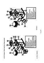
Страница 30: ...Page 29 4 5 Components 4 5 1 B Series Boilerhouse Casing Key Components...
Страница 31: ...Page 30 4 5 2 I Series Internal Casing 21 26 33 Models 44 Models...
Страница 32: ...Page 31 4 5 3 I Series Internal Key Components 21 26 33 Models 44 Models...
Страница 33: ...Page 32 4 5 4 I Series Internal Pump Group 21 26 33 Models 44 Models...
Страница 34: ...Page 33 4 5 5 I Series Internal System Components SK3 4 5 6 I Series Internal Combination Boiler Key Components...
Страница 35: ...Page 34 4 5 7 E Series External Casing 21 26 33 Models 44 Models...
Страница 36: ...Page 35 4 5 8 E Series External Key Components 21 26 33 Models 44 Models...
Страница 37: ...Page 36 4 5 9 E Series External Pump Group 21 26 33 Models 44 Models...
Страница 39: ...Page 38 4 5 12 Combination Boiler Pipe Layout...
Страница 41: ...Page 40 5 1 2 I Series Internal I21 I26 I33 5 1 3 I Series Internal I44...
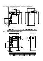
Страница 42: ...Page 41 5 1 4 I Series Internal Combination Boilers I21C I26C I33C 5 1 5 E Series External E21 E26 E33...
Страница 43: ...Page 42 5 1 6 E Series External Base Tray E21 E26 E33 5 1 7 E Series External E44...
Страница 44: ...Page 43 5 1 8 E Series External E44 Base Tray 5 1 9 E Series External Combination Boilers E21C E26C E33C...
Страница 45: ...Page 44 5 1 10 E Series External Combination Boiler Base Tray E21C E26C E33C...
Страница 60: ...Page 59 6 3 2 Wiring Diagram Fuses The appliance must have a permanent live supply connected to operate...
Страница 61: ...Page 60 6 3 3 External 230V Two Channel Programmer Room Thermostat Optional Outdoor sensor...
Страница 62: ...Page 61 6 3 4 Internal Two Channel Programmer and Room Thermostat Optional Outdoor Sensor...
Страница 73: ...Page 72 6 6 9 Honeywell Y Plan Independent CH DHW Fully Pumped Only 2 CHANNEL TIMECLOCK...
Страница 74: ...Page 73 6 6 10 Honeywell S Plan Independent CH DHW Fully Pumped Only 2 CHANNEL TIMECLOCK...
Страница 93: ...Page 92 Kabin Pak External Plume Management Kit KPMK The kit comprises...
Страница 107: ...Page 106 11 4 Burner Start Up Cycle Lock out is indicated by a lamp on the control box...
Страница 122: ...Page 121 14 SPARES 14 1 RDB 2 2 BX Spares...
Страница 124: ...Page 123 14 2 RDB 3 2 BX Spares...
Страница 134: ...Page 133 Intentionally left blank...
Страница 135: ......


