Page
20
1.16 Information Menu
The Information Menu is used to display selected appliance parameters in real time, it can be
used during the commissioning stage, or to assist fault diagnosis.
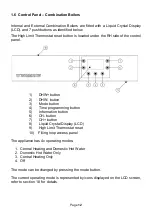
The Information Menu is displayed from the Home Screen by pressing the Information button
(5).
The auxiliary digits then indicate the displayed variable number, and the main digits display the
value of the variable.
If a value is unavailable ‘- -‘ will be displayed on the main digits.
The variables can be scrolled through using the CH+ button (7) and CH- button (6).
To return to the Home Screen, press the Information button (5) again, or if no button is pressed
for 60 seconds, the Home Screen is displayed automatically.
Variable number
Description
1
CH Flow Temperature (°C)
2
CH Return Temperature (°C)
3
DHW Flow Temperature (°C)
4
Heat Store Temperature (°C)
5
System water pressure (bar)
6
DHW Flow rate (l/minute)
7
Circulating pump speed (%)
8
External Temperature (°C)
9
DHW Setpoint (°C)
10
CH Setpoint (°C) (see note)
11
Control PCB Firmware version
12
MMI PCB Firmware version
Note: If the External Temperature sensor is used, the displayed value will be the Weather
Compensated CH setpoint.
Содержание Agentis Series
Страница 2: ......
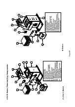
Страница 30: ...Page 29 4 5 Components 4 5 1 B Series Boilerhouse Casing Key Components...
Страница 31: ...Page 30 4 5 2 I Series Internal Casing 21 26 33 Models 44 Models...
Страница 32: ...Page 31 4 5 3 I Series Internal Key Components 21 26 33 Models 44 Models...
Страница 33: ...Page 32 4 5 4 I Series Internal Pump Group 21 26 33 Models 44 Models...
Страница 34: ...Page 33 4 5 5 I Series Internal System Components SK3 4 5 6 I Series Internal Combination Boiler Key Components...
Страница 35: ...Page 34 4 5 7 E Series External Casing 21 26 33 Models 44 Models...
Страница 36: ...Page 35 4 5 8 E Series External Key Components 21 26 33 Models 44 Models...
Страница 37: ...Page 36 4 5 9 E Series External Pump Group 21 26 33 Models 44 Models...
Страница 39: ...Page 38 4 5 12 Combination Boiler Pipe Layout...
Страница 41: ...Page 40 5 1 2 I Series Internal I21 I26 I33 5 1 3 I Series Internal I44...
Страница 42: ...Page 41 5 1 4 I Series Internal Combination Boilers I21C I26C I33C 5 1 5 E Series External E21 E26 E33...
Страница 43: ...Page 42 5 1 6 E Series External Base Tray E21 E26 E33 5 1 7 E Series External E44...
Страница 44: ...Page 43 5 1 8 E Series External E44 Base Tray 5 1 9 E Series External Combination Boilers E21C E26C E33C...
Страница 45: ...Page 44 5 1 10 E Series External Combination Boiler Base Tray E21C E26C E33C...
Страница 60: ...Page 59 6 3 2 Wiring Diagram Fuses The appliance must have a permanent live supply connected to operate...
Страница 61: ...Page 60 6 3 3 External 230V Two Channel Programmer Room Thermostat Optional Outdoor sensor...
Страница 62: ...Page 61 6 3 4 Internal Two Channel Programmer and Room Thermostat Optional Outdoor Sensor...
Страница 73: ...Page 72 6 6 9 Honeywell Y Plan Independent CH DHW Fully Pumped Only 2 CHANNEL TIMECLOCK...
Страница 74: ...Page 73 6 6 10 Honeywell S Plan Independent CH DHW Fully Pumped Only 2 CHANNEL TIMECLOCK...
Страница 93: ...Page 92 Kabin Pak External Plume Management Kit KPMK The kit comprises...
Страница 107: ...Page 106 11 4 Burner Start Up Cycle Lock out is indicated by a lamp on the control box...
Страница 122: ...Page 121 14 SPARES 14 1 RDB 2 2 BX Spares...
Страница 124: ...Page 123 14 2 RDB 3 2 BX Spares...
Страница 134: ...Page 133 Intentionally left blank...
Страница 135: ......

